2.46
SEL-751 Relay Instruction Manual Date Code 20170927
Installation
Arc-Flash Protection: System Installation
Figure 2.41 Clear-Jacketed Fiber Sensor Mounting Example
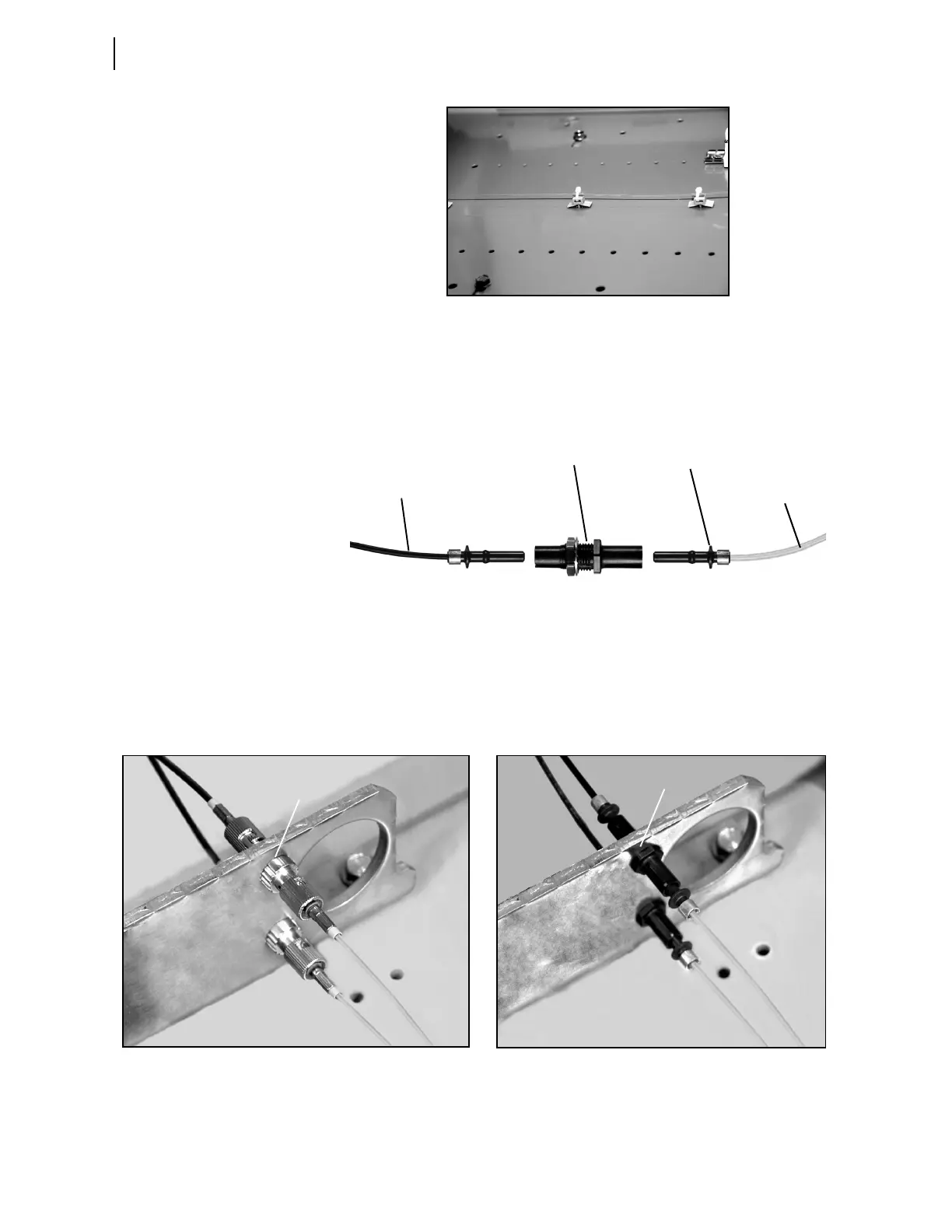
A clear-jacketed fiber sensor consists of the major components shown in
Figure 2.42. Two connector options (V-pin and ST) are available to transition from
the black-jacketed to the clear-jacketed fiber section, as shown in Figure 2.43. The
ST connector option is generally superior because of positive locking.
Figure 2.42 Clear-Jacketed Fiber Sensor Components (V-Pin Style)
For correct operation, a clear-jacketed fiber sensor must be located within 2 m of
the arcing site, with at least 0.5 m of the fiber sensor exposed to the light. The max-
imum length of the clear-jacketed fiber sensor is limited to 70 m and includes both,
clear-jacketed fiber and black-jacketed fiber sections (the black-jacketed section is
counted twice because of its dual-fiber construction). Transition between the two
sections is accomplished by using a connector splice as shown in Figure 2.43.
Figure 2.43 Clear-Jacketed Fiber Sensor Showing Transition From Clear- to Black-Jacketed Fiber Section
Clear-Jacketed
Fiber Sensor
Section
Clear-Jacketed Fiber
Transition Connectors
(V-Pin)
Connector Splice
Bushing (V-Pin)
Black-Jacketed
Fiber Section
ST Connection (3/8” diameter hole) V-Pin Connection (5/16” diameter hole)
5/16” diameter hole
3/8” diameter hole