4.64
SEL-751 Relay Instruction Manual Date Code 20170927
Protection and Logic Functions
Group Settings (SET Command)
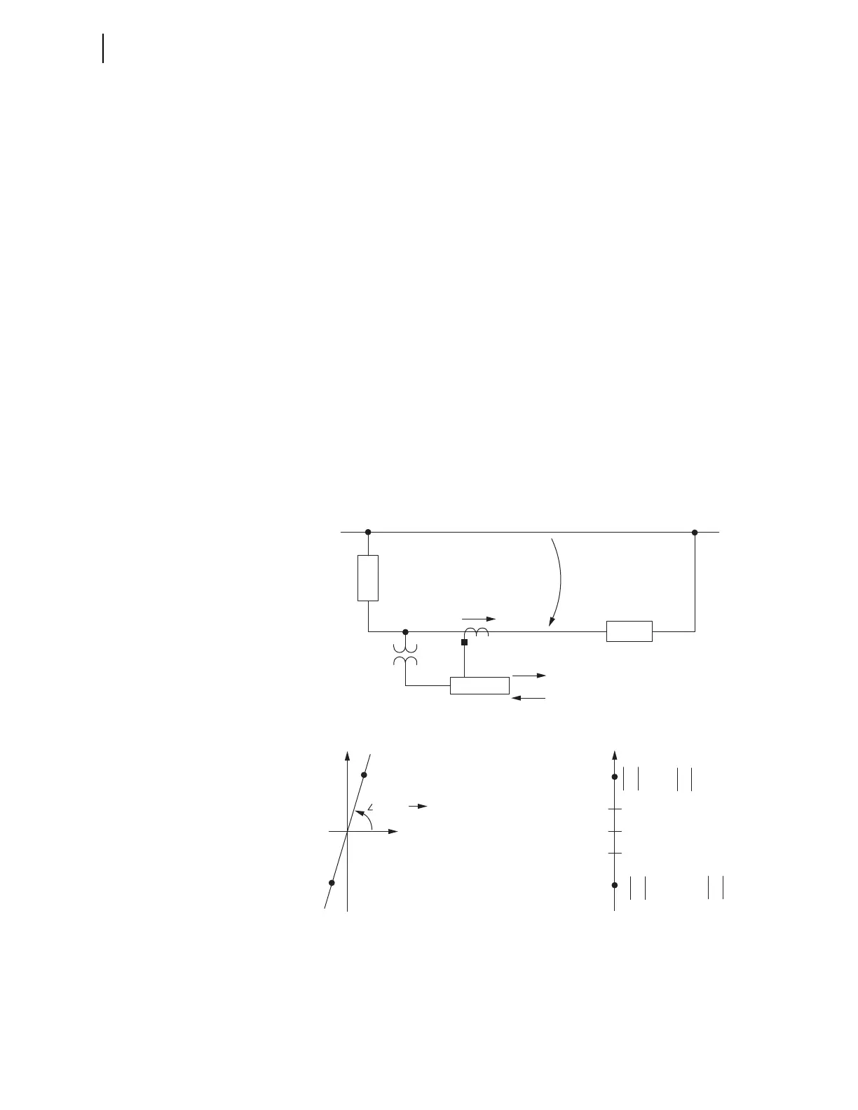
Deriving Z0F and Z0R Settings. Figure 4.44 shows the voltage and current
polarity for an SEL-751 in a zero-sequence impedance network (the same
approach can be instructive for negative-sequence impedance analysis, too).
For a forward fault, the SEL-751 effectively sees the sequence impedance
behind it as:
Z
M
= V
0
/(–I
0
) = –(V
0
/I
0
)
V
0
/I
0
= –Z
M
(what the relay sees for a forward fault)
For a reverse fault, the SEL-751 effectively sees the sequence impedance in
front of it:
Z
N
= V
0
/I
0
V
0
/I
0
= Z
N
(what the relay sees for a reverse fault)
If the system in Figure 4.44 is a solidly-grounded system (mostly inductive;
presume uniform system angle), and the load is connected line-to-neutral, the
impedance plot (in the R + jX plane) would appear as in Figure 4.45a, with
resultant Z0F and Z0R settings as in Figure 4.45b. The zero-sequence line
angle noted in Figure 4.45a (Z0MTA) is the same angle found in
Figure 4.27 and Figure 4.29 (in the equation box with the Enable line).
The preceding method of automatically making settings Z0F and Z0R (where
both Z0F and Z0R are positive values and Z0R > Z0F) usually suffices for
mostly inductive systems—Figure 4.44 and Figure 4.45 just provide a theoret-
ical background.
Figure 4.44 Zero-Sequence Impedance Network and Relay Polarity
Figure 4.45 Zero-Sequence Impedance Plot for Solidly-Grounded, Mostly
Inductive System
I
0
V
0
Z
N
Z
M
Forward
Reverse
Zero-Sequence Reference Bus
SEL-751
(a) Impedance Plot (b) Z0F and Z0R Settings
Z
N
= R
N
+ jX
N
(Reverse)
–Z
M
= —R
M
— jX
M
(Forward)
R
jX
Reverse
Forward
0
Z
Z0F
Z0R
Z
N
— Z
M
Z
N
> Z0R
Z0F > — Z
M
Z0R > Z0F
Zero-Sequence Line Angle
(Setting Z0ANG)
Z0MTA