4.12
SEL-751 Relay Instruction Manual Date Code 20170927
Protection and Logic Functions
Group Settings (SET Command)
The phase instantaneous overcurrent elements (50P1 through 50P4; see
Figure 4.2) normally operate by using the output of the one cycle cosine-fil-
tered phase current. During severe CT saturation, the cosine-filtered phase
current magnitude can be substantially reduced because of the high harmonic
content and reduced magnitude of the distorted secondary waveform. If the
overcurrent element relied only on the output of the cosine-filtered secondary
current, the operation of any high-set instantaneous overcurrent element might
be severely delayed and jeopardized. For any phase instantaneous overcurrent
element in the SEL-751 that is set greater than eight times the relay current
input rating (40 A in a 5 A relay), the overcurrent element also operates on the
output of a bipolar peak detector if the current waveform is highly distorted, as
is the case with severe CT saturation. This ensures fast operation of the 50Pn
phase overcurrent elements even with severe CT saturation.
When the harmonic distortion index exceeds the fixed threshold, which indi-
cates severe CT saturation, the phase overcurrent elements operate on the out-
put of the peak detector. When the harmonic distortion index is below the
fixed threshold, the phase overcurrent elements operate on the output of the
cosine filter.
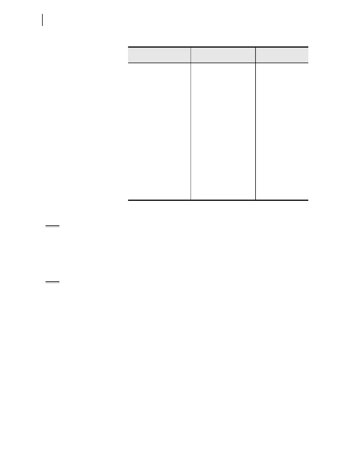
Table 4.8 Maximum Phase Overcurrent Settings
Setting Prompt Setting Range
Setting Name :=
Fac to ry Default
MAXP OC TRIP LVL OFF, 0.25–100.00 A
a
0.05–20.00 A
b
a
For I
NOM
= 5 A.
b
For I
NOM
= 1 A.
50P1P := 10.00
50P1P := 2.00
MAXP OC TRIP DLY OFF, 0.00–400.00 sec 50P1D := 0.00
MAXP OC TRQ CON SEL
OGIC 50P1TC := 1
MAXP OC TRIP LVL OFF, 0.25–100.00 A
a
0.05–20.00 A
b
50P2P := 10.00
50P2P := 2.00
MAXP OC TRIP DLY OFF, 0.00–400.00 sec 50P2D := 0.00
MAXP OC TRQ CON SEL
OGIC 50P2TC := 1
MAXP OC TRIP LVL OFF, 0.25–100.00 A
a
0.05–20.00 A
b
50P3P := 10.00
50P3P := 2.00
MAXP OC TRIP DLY OFF, 0.00–400.00 sec 50P3D := 0.00
MAXP OC TRQ CON SEL
OGIC 50P3TC := 1
MAXP OC TRIP LVL OFF, 0.25–100.00 A
a
0.05–20.00 A
b
50P4P := 10.00
50P4P := 2.00
MAXP OC TRIP DLY OFF, 0.00–400.00 sec 50P4D := 0.00
MAXP OC TRQ CON SEL
OGIC 50P4TC := 1
NOTE: The cosine filter provides
excellent performance in removing dc
offset and harmonics. However, the
bipolar peak detector has the best
performance in situations of severe
CT saturation when the cosine filter
magnitude estimation is significantly
degraded. Combining the two
methods provides an elegant solution
for ensuring dependable short-circuit
overcurrent element operation.
NOTE: When using the output of
harmonic blocking logic to torque-
control 50 elements set with a pickup
greater than 8 • INOM, the harmonic
blocking could nullify the peak
detector feature of the
corresponding 50 element. Refer to
the Second- and Fifth-Harmonic
Blocking Logic on page 4.86.