4.68
SEL-751 Relay Instruction Manual Date Code 20170927
Protection and Logic Functions
Group Settings (SET Command)
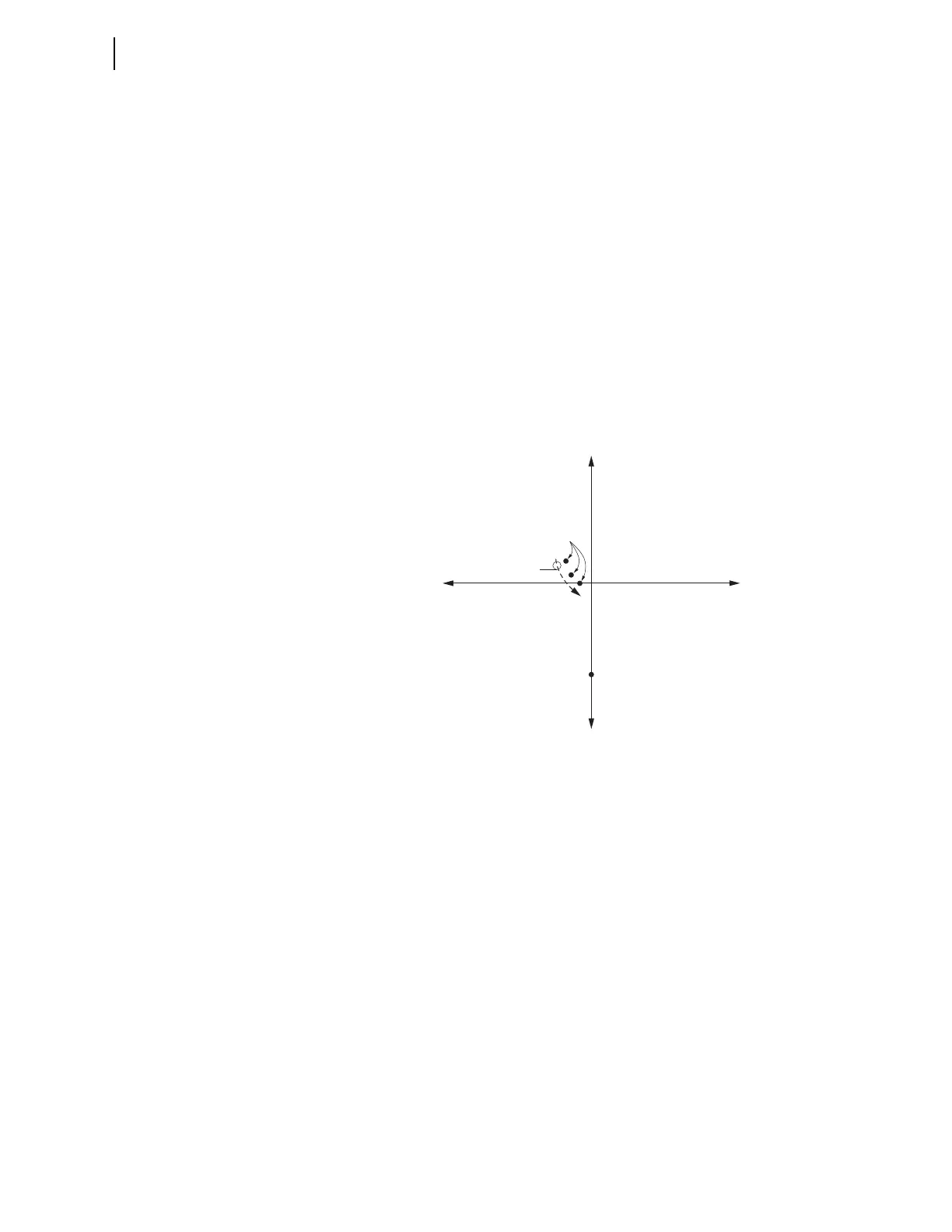
The zero-sequence voltage/current vector values of Figure 4.49 are converted
(using polarity and impedances in Figure 4.47) to the apparent zero-sequence
impedances that the respective relays see, as plotted in Figure 4.50:
➤ Ground fault on Feeder 1 is in the forward direction for
Relay 1:
V
0
/(–I
0(1)
) = parallel combination of zero-sequence impedance
values –jXC
0(2)
, –jXC
0(n)
, and 3R
G
+ Z
0T
V
0
/I
0(1)
= –(parallel combination of zero-sequence impedance
values –jXC
0(2)
, –jXC
0(n)
, and 3R
G
+Z
0T
)
V
0
/I
0(1)
= the negative value of the aggregate zero-sequence
impedance behind Relay 1
➤ Ground fault on Feeder 1 is in the reverse direction for Relay 2:
V
0
/I
0(2)
= –jXC
0(2)
V
0
/I
0(2)
= the zero-sequence capacitive reactance for Feeder 2
in front of Relay 2
Figure 4.50 Zero-Sequence Impedance Plots for Ground Fault on Low-
Impedance Grounded Distribution System
Presuming that all of the feeders in this distribution substation example have
roughly the same amount of capacitance-creating network (e.g., underground
cable), then the following applies:
➤ The Relay 1 apparent zero-sequence impedance plot in
Figure 4.50 is representative of a ground fault in front of any
relay in the substation (forward fault).
➤ The Relay 2 apparent zero-sequence impedance plot in
Figure 4.50 is representative of a ground fault behind any relay
in the substation (e.g., a ground fault on another parallel feeder;
reverse fault).
The forward/reverse impedance plots in Figure 4.50 appear asymmetric, espe-
cially when compared to Figure 4.45(a) for a solidly grounded system with
sources at each end. The Z0MTA setting in Figure 4.45(a) would (by inspec-
tion) be approximately 75 degrees.
Contrastingly, the Z0MTA setting for Figure 4.50 has to allow the forward/
reverse characteristic to fit in between the forward/reverse impedance plots.
The forward impedance plot is the most critical to accommodate—one defi-
R
0
jX
0
—jX
0
Relay 2
(reverse fault)
Relay 1
(forward fault)
—R
0
Decreasing R
G