D.20
SEL-751 Relay Instruction Manual Date Code 20170927
DNP3 Communications
DNP3 Documentation
Default Data Map
The default data map is an automatically generated subset of the reference
map. All data maps are initialized to the default values, based on the SEL-751
part number. Table D.11 shows the SEL-751 default data map. If the default
maps are not appropriate, you can also use the custom DNP mapping
commands SET DNP and SHOW DNP to create the map necessary for your
application.
10,12 OC Pulse Open Circuit Breaker command
10,12 CC Pulse Close Circuit Breaker command
10,12 OC:CC Open/Close pair for Circuit Breaker
Counters
20, 22 SCxx SELOGIC Counter Values (xx = 01–32)
GROUP Active Settings Group
Analog Inputs
30, 32, 34 IA_MAG–RA128
b,c
Analog Quantities from Ta ble L .1 with an “x” in
the DNP column
SER_NUM Serial Number
0Numeric 0
1Numeric 1
Analog Outputs
40, 41 RAxxx Remote Analogs (RA001 to RA128)
GROUP Active Settings Group
NOOP No operation, no error
a
Valid Relay Word bits depend on the relay model.
b
Valid analog inputs depend on the relay model.
c
Refer to Default Analog Inputs for default analog input scaling and dead bands.
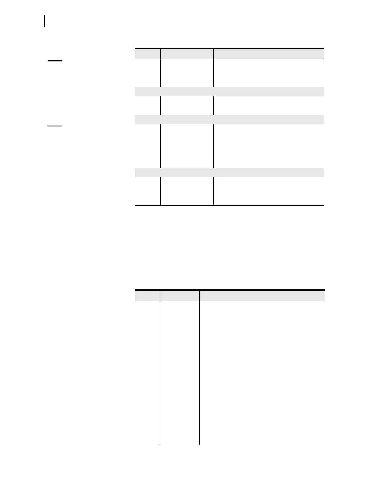
Table D.10 DNP3 Reference Data Map (Sheet 2 of 2)
Object Labels Description
NOTE: When setting EN_LRC := Y
(see Table 9.4), the Relay Word bit
LOCAL supervises the CC and OC
bits. If the LOCAL bit is asserted
(LOCAL = 1), the relay does not set
the CC or OC bits. The Relay Word bit
LOCAL is determined by the LOCAL
SEL
OGIC control equation (see
Tab le 9.4 ).
NOTE: All fault information analog
inputs contain data from the latest
captured event (See Appendix L:
Analog Quantities).
Ta b l e D.1 1 D N P 3 Defa ul t Da ta M a p (Sheet 1 of 2)
Object Default Index Point Label
01, 02 0 ENABLED
1 TRIP_LED
2 TLED_01
3 TLED_02
4 TLED_03
5 TLED_04
6 TLED_05
7 TLED_06
8STFAIL
9 STSET
10 IN101
11 IN102
12–99 A portion of these binary inputs can have default values as
described in Default Binary Inputs on page D.21. Outside
that scope, they contain the value NA.
10, 12 0–31 RB01–RB32 Remote Bits