4.104
SEL-751 Relay Instruction Manual Date Code 20170927
Protection and Logic Functions
Group Settings (SET Command)
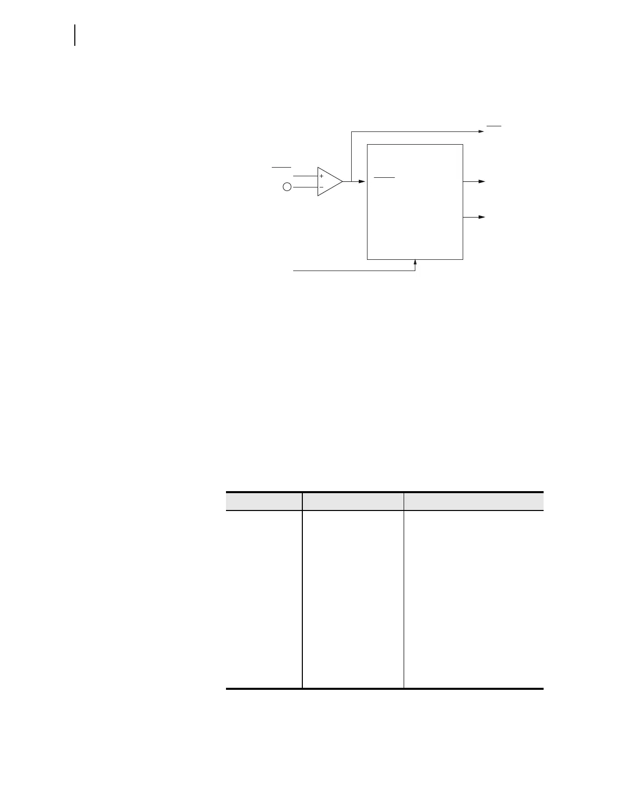
Figure 4.65 shows the inputs, settings and outputs of the inverse-time
overvoltage element.
n = 1, 2, 3, or 4. q Refer to
Table 4.39
.
Figure 4.65 Logic Diagram of the Inverse-Time Overvoltage Element
When the fundamental frequency component of the operating quantity
exceeds the pickup setting, 59InP, Relay Word bit 59In asserts. The timer
won't start to integrate unless the operating quantity exceeds 1.025 • 59InP.
The inverse-time overvoltage protection element has the characteristic defined
by Equation 4.15.
Equation 4.15
The settings used are listed in Table 4 .40.
The SEL-751 provides four curve options for each of the 59I elements, setta-
ble via the 59InCRV setting—CURVEA, CURVEB, CURVEC, and COEF
(user-programmable curve). The characteristics of Curve A, Curve B, and
Curve C are shown in Figure 4.66.
Table 4.40 Inverse-Time Overvoltage Settings
Setting Prompt Setting Range Setting Name := Factory Default
59I ENABLE Y, N E59In := N
OPERATING QTY Refer to Ta ble 4.39 59InOQ := VAB
PICKUP LVL Refer to Tab le 4.39 59InP := 120.00
CURVE CURVEA, CURVEB,
CURVEC, COEF
59InCRV := CURVEA
COEFF A 0.00–6.00 59InCFA := 3.88
COEFF B 0.00–3.00 59InCFB := 0.96
COEFF C 0.01–3.00 59InCFC := 2.00
TIME DIAL 0.00–16.00 59InTD := 1.00
RESET TIME 0.00–1.00 sec 59InTTR := 0.01
TRQ CONTROL SEL
OGIC 59InTC := 1
Settings
Relay
Word
Bits
59I Inverse-Time
Overvoltage Element
Settings
59InP Pick up value
59InCRV Curve selection
59InCFA Coefficient A
59InCFB Coefficient B
59InCFC Coefficient C
59InTD Time dial
59InTTR Time to reset
59InTC Torque control
59In
59InT
59InRS
59InP
59InOQ
59InTC
1
TTT
n
59InTD
59InCFB
59In CFA
59InOQ
59InP
---------------------
59InCFC
1–
--------------------------------------------------------+
=