4.136
SEL-751 Relay Instruction Manual Date Code 20170927
Protection and Logic Functions
Group Settings (SET Command)
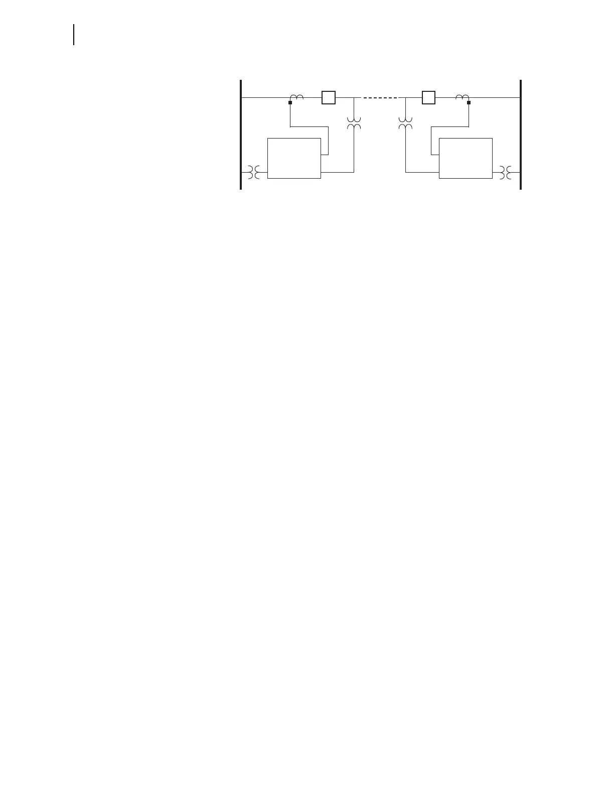
Figure 4.83 SEL-751 Relays Installed at Both Ends of a Transmission Line in
a High-Speed Reclose Scheme
SEL-751 (1) Relay
Before allowing circuit breaker 52/1 to be reclosed after an open interval
time-out, the SEL-751(1) checks that Bus 1 voltage is hot and the
transmission line voltage is dead. This requires reclose supervision settings:
79CLSD := 0.00 seconds (only one check)
79CLS := 59VP AND 27S1
SEL-751 (2) Relay
The SEL-751(2) checks that Bus 2 voltage is hot, the transmission line
voltage is hot, and in synchronism after the reclosing relay open interval
times out, before allowing circuit breaker 52/2 to be reclosed. This requires
reclose supervision settings:
79CLSD := 0.00 seconds (only one check)
79CLS := 25A1
Other Setting Considerations for SEL-751(1) and SEL-751(2) Relays
Refer to Skip Shot (79SKP) and Stall Open Interval Timing (79STL) Settings
on page 4.147.
SEL
OGIC control equation setting 79STL stalls open interval timing if it
asserts to logical 1. If setting 79STL is deasserted to logical 0, open interval
timing can continue. The SEL-751(1) has no intentional open interval timing
stall condition (circuit breaker 52/1 closes first after a transmission line fault):
79STL := 0
The SEL-751(2) starts open interval timing after circuit breaker 52/1 at the
remote end has re-energized the line. The SEL-751(2) has to see Bus 2 hot,
transmission line hot, and in synchronism across open circuit breaker 52/2 for
open interval timing to begin. Thus, SEL-751(2) open interval timing is
stalled when the transmission line voltage and Bus 2 voltage are not in syn-
chronism across open circuit breaker 52/2:
79STL := NOT 25A1
where:
59VP = Bus 1 is hot
27S1 = monitored single-phase transmission line voltage
(channel VS) is dead
where:
25A1 = selected Bus 2 phase voltage (VA, VB, or VC) is in
synchronism with monitored single-phase
transmission line voltage (channel VS) and both
are hot
52/1
52/2
SEL-751 (1)
IA, IB, IC
VS
SEL-751 (2)
IA, IB, IC
VA, VB, VC
VS
Bus 1 Bus 2
3-Phase 3-Phase
1-Phase
VA, VB, VC