4.115
Date Code 20170927 Instruction Manual SEL-751 Relay
Protection and Logic Functions
Group Settings (SET Command)
Set 25ANG2 = 25° and use the resultant synchronism-check element in man-
ual close logic to supervise manual closing (for example, assert IN301 to initi-
ate manual close), e.g.,
CL := IN301 AND (25A2 OR …) (see Figure 4.80)
In this example, the angular difference across the circuit breaker can be
greater for a manual close (25 degrees) than for an automatic reclose
(15 degrees).
A single output contact (e.g., OUT102 := CLOSE) can provide the close func-
tion for both automatic reclosing and manual closing (see Figure 4.80 for
logic output).
Power Elements
You can enable as many as two independent three-phase power elements in the
SEL-751. Each enabled element can be set to detect real power or reactive
power. When voltage inputs to the relay are from delta-connected PTs or when
you use a single voltage input, the relay cannot account for unbalance in the
voltages in calculating the power. When you use one voltage (only the VA or
VAB) and set SINGLEV := Y, the relay assumes that the system voltages are
balanced in both magnitude and phase angle. Power and power factor are cal-
culated assuming balanced voltages. Take this into consideration in applying
the power elements.
With SEL
OGIC control equations, the power elements provide a wide variety
of protection and control applications. Typical applications are:
➤ Overpower and/or underpower protection/control
➤ Reverse power protection/control
➤ VAR control for capacitor banks
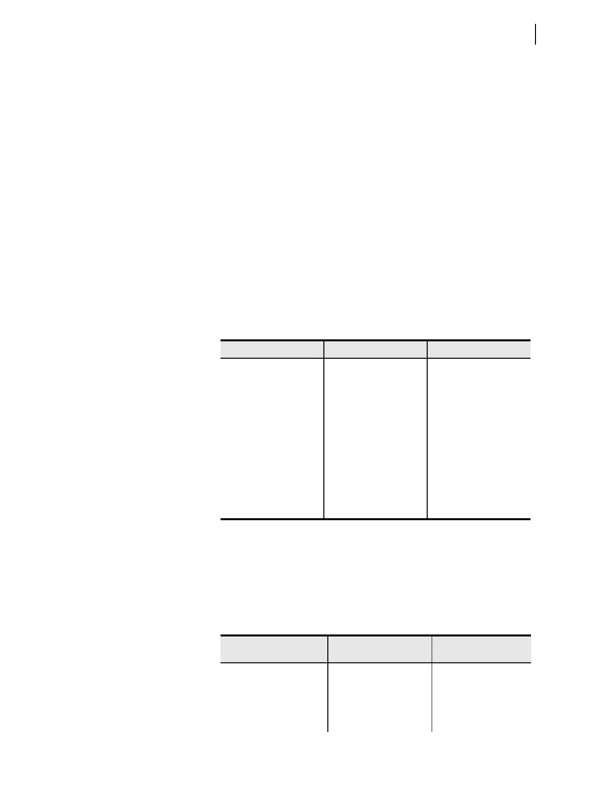
Table 4.43 Voltages When Setting SINGLEV := Y
DELTA_Y Setting PHROT Setting Voltages
WYE ABC VA = |Va| °
VB = |Va| –120°
VC = |Va| +120°
WYE ACB VA = |Va|
VB = |Va| +120
VC = |Va| –120
DELTA ABC VAB = |Vab|
VBC = |Vab| –120
VCA = |Vab| +120
DELTA ACB VAB = |Vab|
VBC = |Vab| +120
VCA = |Vab| –120
Table 4.44 Power Element Settings (Sheet 1 of 2)
Setting Prompt Setting Range
Setting Name :=
Fac to ry Defa ult
ENABLE PWR ELEM N, 3P1, 3P2 EPWR := N
3PH PWR ELEM PU OFF, 1.0–6500.0 VA
a
(sec-
ondary)
3PWR1P := OFF
PWR ELEM TYPE +WATTS, –WATTS,
+VARS, –VARS
PWR1T := +VARS