2.32
SEL-751 Relay Instruction Manual Date Code 20170927
Installation
AC/DC Control Connection Diagrams
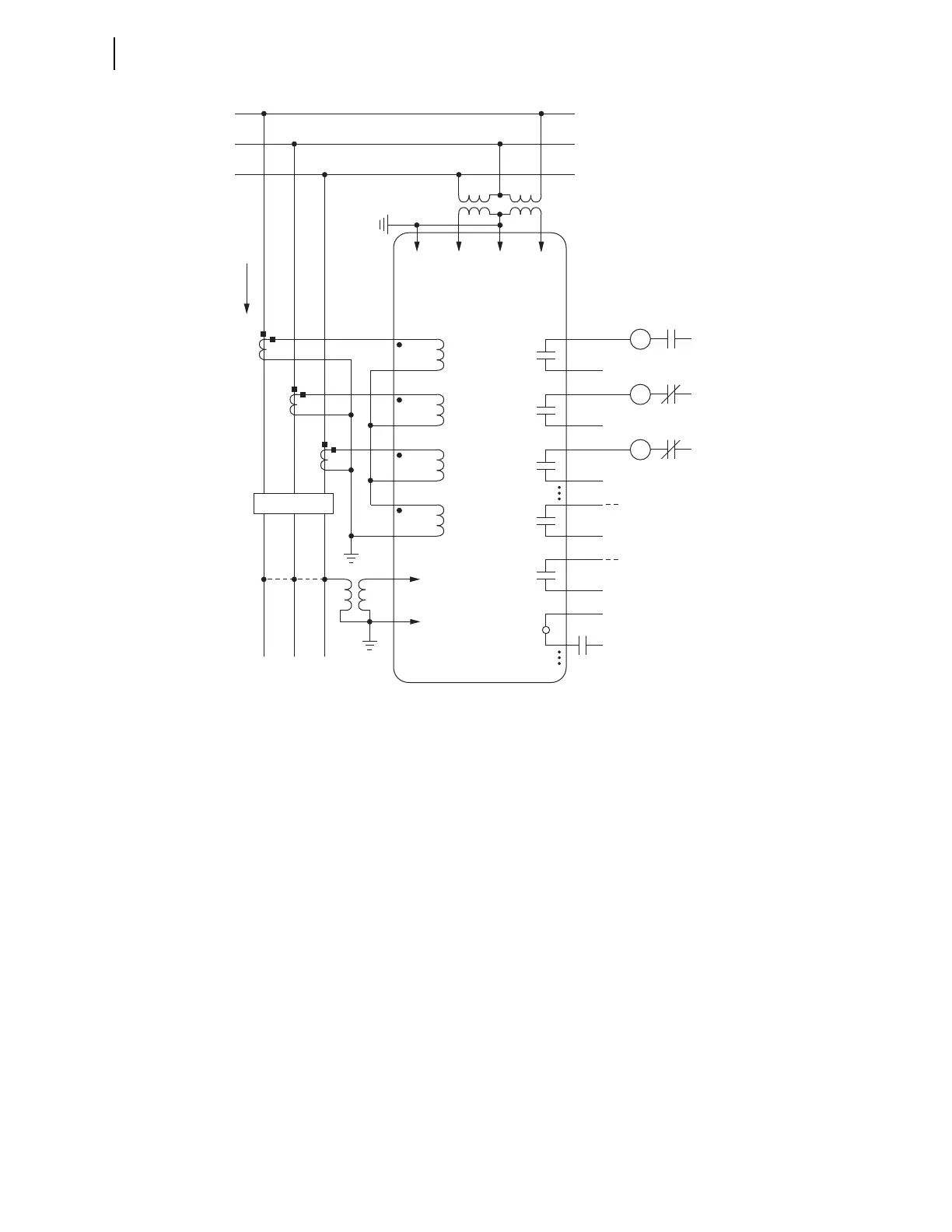
Voltages are necessary for voltage elements, synchronism-check elements, voltage-polarized directional elements, fault
location, and metering (e.g., voltage, KW, KVAR). INxxx and OUTxxx indicate user-configurable optional digital inputs and
outputs. Voltage channel VS is shown connected with VSCONN := VS for use in voltage and synchronism-check elements
and voltage metering. You can use the VS voltage channel for other voltage inputs such as 3VO from a broken delta PT
connection by setting VSCONN := 3V0 for use with zero-sequence voltage polarized directional elements. Setting
VSCONN := 3V0 disables synchronism-check elements.
Channel IN provides current I
N
for the neutral ground overcurrent elements. Separate from Channel IN, the residual
ground overcurrent elements operate from the internally derived residual current I
G
(I
G
= 3I
0
= I
A
+ I
B
+ I
C
). But in this
residual connection example, the neutral ground and residual ground overcurrent elements operate the same because
I
N
= I
G
.
Figure 2.23 SEL-751 Provides Overcurrent Protection and Reclosing for a Distribution Feeder
(Includes Fast Bus Trip Scheme) (Delta-Connected PTs)
TC
Trip
Coil
52A
(+)
(—)
Trip
Circuit
IA
C
B
A
SEL-751 RELAY
OUT103
CC
Close
Coil
52B
(+)
(—)
Close
Circuit
IB OUT102
86
Lock
Out
86B
(+)
(—)
Breaker
Failure
Trip
Circuit
IC OUTxxx
IN
FEEDER
52
(+)
OUTxxx
(+)
52A
to Annunciator, RTU,
SEL-2032/2030/2020,
or SEL-3530 RTAC
to Bus Relay
(Fast Bus Trip Scheme)
ALARM
OUT101
(+)
(—)
Breaker Status
INxxx
VCNVBVA
VS
NS
Forward
Tripping
Direction