4.43
Date Code 20170927 Instruction Manual SEL-751 Relay
Protection and Logic Functions
Group Settings (SET Command)
q From Figure 4.29 and Figure 4.31; w to Figure 4.32 and Figure 4.33; e from Figure 4.25.
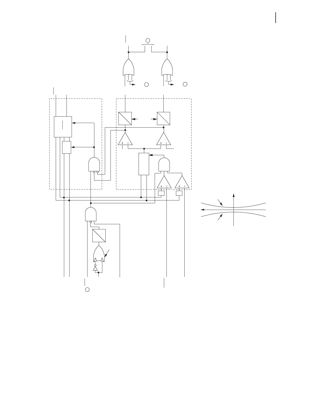
Figure 4.30 Wattmetric and Incremental Conductance Directional Elements (Petersen Coil-Grounded Systems)
The 3V0 input to Figure 4.30 may be either a calculated value (when
VSCONN := VS and DELTA_Y := WYE) or a measured value (when
VSCONN := 3V0). See Zero-Sequence Voltage Sources on page 4.33.
P
0
Reverse
Threshold
Forward
Threshold
Q
0
Zero-Sequence
Power Plane
Forward Threshold = —DIRWFP • 0.95 — |3V
0
• I
N
*| • 0.05
DIRWFP = Wattmetric Forward Pickup (W Secondary) DIRWRP = Wattmetric Reverse Pickup (W Secondary)
Reverse Threshold = DIRWRP • 0.95 + |3V
0
• I
N
*| • 0.05
Re(3V
0
•I
N
*)
Enable
0
DIRWD
0
DIRWD
Forward
Reverse
RDIRW
FDIRW
Delay
Setting
(Cyc)
Reverse
Threshold
Forward
Threshold
Wattmetric Element
Buffer
Enable
Enable
FDIRC
RDIRC
Forward
Reverse
Incremental Conductance Element
CYC
30
0
Rising Edge Detects
0.005 A
Secondary
59RES
(V Secondary)
52A
(Breaker
Opening and
Closing)
Enable
DIRNE
3V
0
I
N
"P" listed in
setting ORDER
( )
Re
ΔI
N
Δ3V
0
RDIRN
FDIRN
Relay
Word
Bits
Relay
Word
Bits
"Forward"
Outputs
"Reverse"
Outputs
|•|
|•|
Relay
Word
Bits
Setting
3
2
1
1