1.9
Date Code 20170927 Instruction Manual SEL-751 Relay
Introduction and Specifications
Getting Started
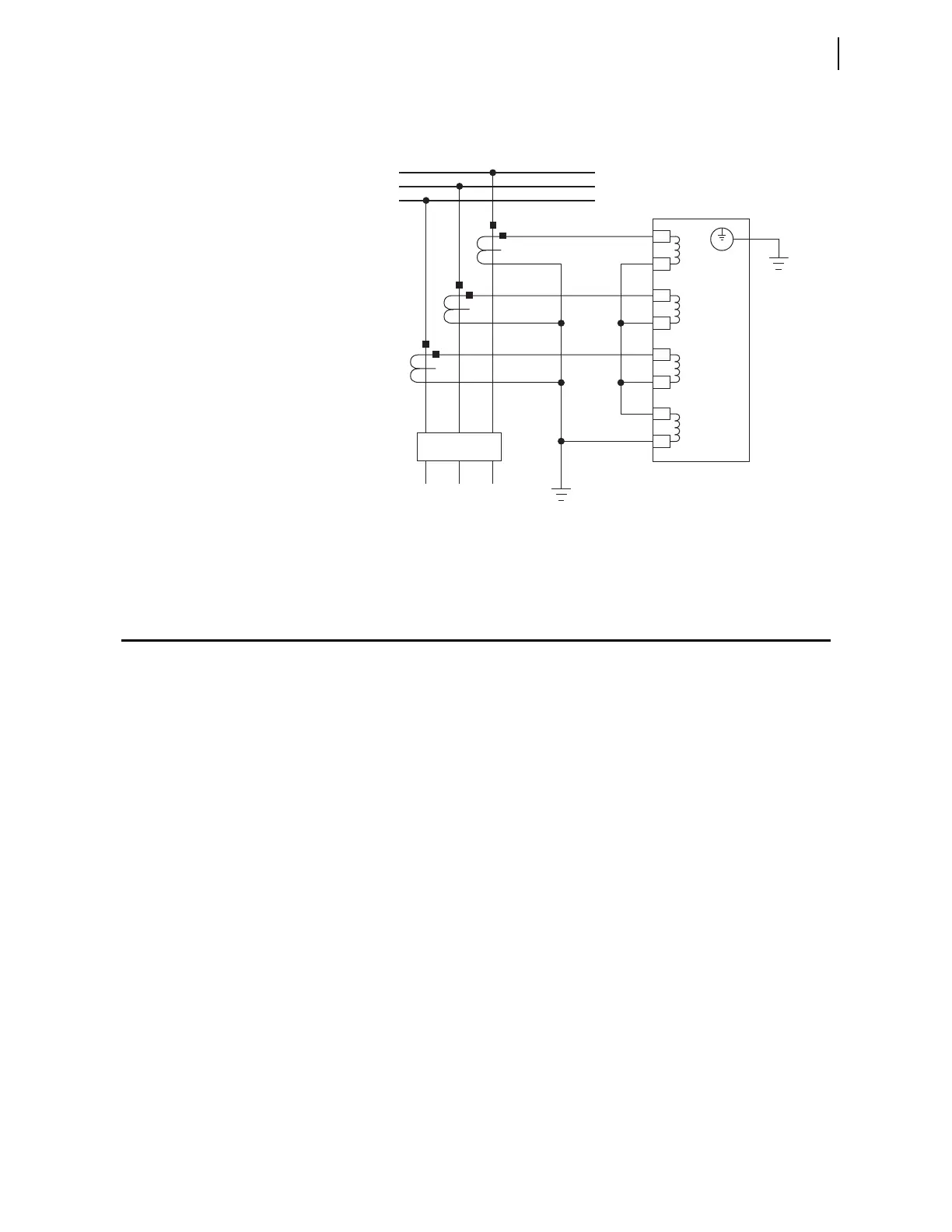
Figure 1.2 shows typical current connections. Refer to Section 2: Installation
for additional applications and the related connection diagrams.
Figure 1.2 Typical Current Connections
Getting Started
Understanding basic relay operation principles and methods will help you use
the SEL-751 effectively. This section presents the fundamental knowledge
you need to operate the SEL-751, organized by task. These tasks help you
become familiar with the relay and include the following:
➤ Powering the relay
➤ Establishing communication
➤ Checking relay status
➤ Setting the date and time
Perform these tasks to gain a fundamental understanding of relay operation.
Powering the Relay
Power the SEL-751 with 110–240 Vac/110–250 Vdc or 24–48 Vdc,
depending on the part number.
➤ Observe proper polarity, as indicated by the +/H (Terminal A01)
and the –/N (Terminal A02) on the power connections.
➤ Connect the ground lead; see Grounding (Earthing)
Connections on page 2.23.
➤ Once connected to power, the relay does an internal self-check
and the ENABLED LED illuminates.
SEL-751
The current transformers and the SEL-751
chassis must be grounded in the relay cabinet.
A
B
C
IN
IC
IB
IA
Z08
Z07
Z06
Z05
Z04
Z03
Z02
Z01
52
FEEDER
BUS