4.178
SEL-751 Relay Instruction Manual Date Code 20170927
Protection and Logic Functions
Global Settings (SET G Command)
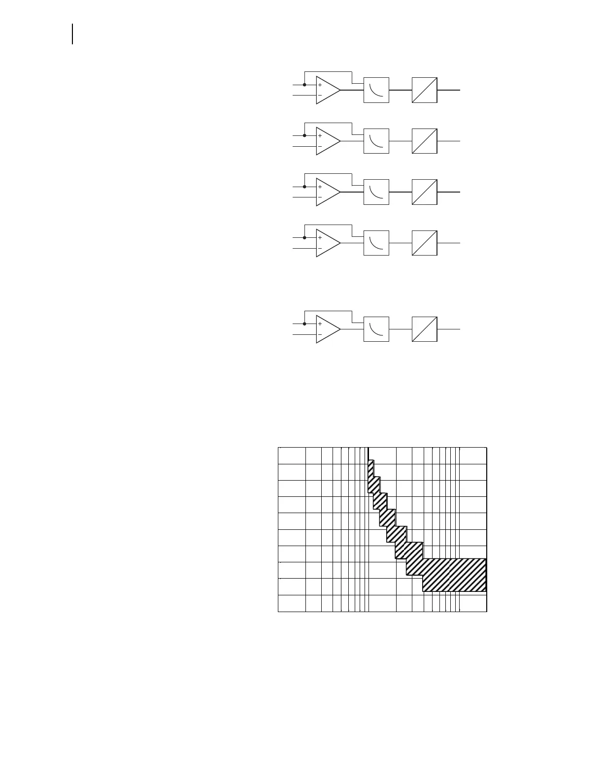
Figure 4.103 Inverse Time-Overlight Element Logic
Figure 4.104 shows the inverse time-overlight element curve shape. The ele-
ment uses 32 samples per cycle data, processed 16 times per cycle. TOL ele-
ment algorithm ensures that the light must be present for a minimum of two
samples, regardless of the light level. It also ensures that for low light levels,
element operation cannot be delayed for more than ¼ of a power system cycle.
Figure 4.104 TOL Element Inverse Curve Characteristic
Setting the Arc-Flash Time-Overlight Element
Given the critical nature of the arc-flash protection function it is recommended
that the element be set based on the ambient light level. This approach guaran-
tees maximum sensitivity coupled with the fastest tripping time.
PU: 0
DO: 1 cycle
ITOL2
LS2
Setting
TOL2P
TOL2
PU: 0
DO: 1 cycle
ITOL1
LS1
Setting
TOL1P
TOL1
PU: 0
DO: 1 cycle
ITOL3
LS3
Setting
TOL3P
TOL3
PU: 0
DO: 1 cycle
ITOL4
LS4
Setting
TOL4P
TOL4
PU: 0
DO: 1 cycle
ITOL8
LS8
Setting
TOL8P
TOL8
•
•
•
10
-1
10
0
10
1
0
0.5
1
1.5
2
2.5
3
3.5
4
4.5
5
Multiples of TOL Pickup
Time [1/16 cycle]