4.45
Date Code 20170927 Instruction Manual SEL-751 Relay
Protection and Logic Functions
Group Settings (SET Command)
q From Figure 4.24; w from Figure 4.25; e from Figure 4.73;
r from Figure 4.26; t from Figure 4.27; y from Figure 4.28;
u from Figure 4.29, Figure 4.30, or Figure 4.31; i to Figure 4.34.
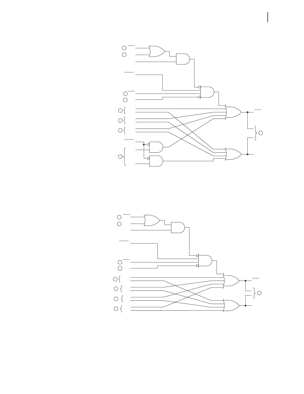
Figure 4.32 Routing of Directional Elements to Residual Ground
Overcurrent Elements
q From Figure 4.24; w from Figure 4.25; e from Figure 4.73;
r from Figure 4.26; t from Figure 4.27; y from Figure 4.28;
u from Figure 4.29, Figure 4.30, or Figure 4.31; i to Figure 4.35.
Figure 4.33 Routing of Directional Elements to Neutral Ground Overcurrent
Elements
The 3V0 input to Figure 4.30 may be either a calculated value (when
VSCONN := VS and DELTA_Y := WYE) or a measured value (when
VSCONN := 3V0). See Zero-Sequence Voltage Sources on page 4.33.
LOP
Relay
Word
Bits
DIRVE
DIRNE
FDIRQG
RDIRQG
VSCONN := 3V0
DIRIE
Relay
Word
Bits
DIRGF
(Forward)
DIRGR
(Reverse)
Relay
Word
Bits
Setting
Setting
EFWDLOP = Y
FDIRV
RDIRV
Loss-of-Potential
FDIRI
RDIRI
ORDER = P
(contains P by itself)
FDIRN
RDIRN
1
1
2
3
4
5
6
7
8
LOP
Relay
Word
Bits
DIRVE
DIRNE
FDIRQG
RDIRQG
VSCONN := 3V0
DIRIE
Relay
Word
Bits
DIRNF
(Forward)
DIRNR
(Reverse)
Relay
Word
Bits
Setting
EFWDLOP = Y
FDIRV
RDIRV
Loss-of-Potential
FDIRI
RDIRI
FDIRN
RDIRN
1
1
2
3
4
5
6
7
8