9.3
Date Code 20170927 Instruction Manual SEL-751 Relay
Bay Control
Overview
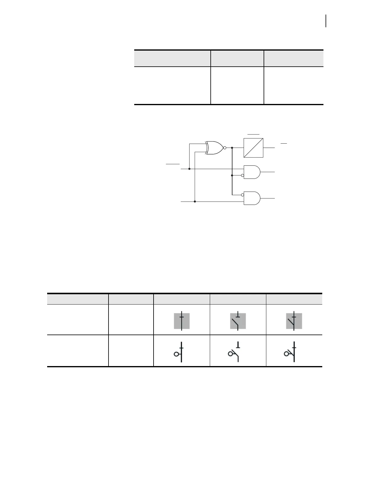
Figure 9.1 Dual-Point Disconnect Status Logic
Table 9.3 provides typical ANSI and IEC disconnect symbols that are
available to use in bay screen design. Column 1 identifies the standard (ANSI/
IEC) and the type of disconnect. Column 2 identifies the interior color
property of the disconnect. Columns 3, 4, and 5 identify closed, open, and
alarm states of the disconnect. For a complete list of ANSI and IEC disconnect
symbols available to use with the bay screens, refer to the
ACSELERATOR Bay
Screen Builder SEL-5036 Software Instruction Manual.
Local/Remote
Breaker Control
The SEL-751 supports local/remote breaker control functionality through
supervision of the OC and CC breaker control Relay Word bits. The
supervision of these breaker control Relay Word bits can be enabled or
disabled with the global setting EN_LRC (see Table 9.4). To enable local/
remote supervision of the breaker control Relay Word bits, set EN_LRC := Y.
When EN_LRC := Y, the LOCAL SEL
OGIC control equation is available.
Table 9.2 Disconnect Settings
a
a
n = 1, 2, 3, 4, or 5
Setting Prompt Setting Range
Setting Name :=
Fac to ry Default
DISCONNECT n N/O CONTACT
SEL
OGIC 89A2Pn := 0
DISCONNECT n N/C CONTACT
SELOGIC 89B2Pn := NOT 89A2Pn
DISCONNECT n ALARM
TIMER
0.00–300.00 sec 89A2PnD:=5.00
89A2PnD
0
Alarm Timer
Setting
89AL2Pn
89CL2Pn
89OP2Pn
89A2Pn
89B2Pn
Relay
Word
Bits
Relay
Settings
n = 1, 2, 3, 4, or 5
Table 9.3 Two-Position Disconnect Symbols
Type Interior Color State 1 (Closed) State 2 (Open) State 3 (Alarm)
ANSI and IEC Disconnect Gray
ANSI and IEC Motor-
Operated Disconnect
Transparent