4.171
Date Code 20170927 Instruction Manual SEL-751 Relay
Protection and Logic Functions
Global Settings (SET G Command)
EXAMPLE 4.34 Setting MPTXxx Using the Default Location of
Analog Quantity
MPTX01 := THE LOAD CURRENT IS
MPAQ01 value = 157.44
Formatted message out when triggered: THE LOAD CURRENT IS 157
Location and resolution of the analog quantity value within the message
can be specified by using “%.pf”,
where
% defines location of the value
p defines number of digits (as many as 6, defaults to 6 if
omitted)
f indicates floating point value (use %d if nearest whole
number is desired)
EXAMPLE 4.35 Setting MPTXxx With a Specified Location of
Analog Quantity
MPTX01 := THE LOAD CURRENT IS %.2f AMPERES
MPAQ01 value = 157.44
Formatted message out when triggered: THE LOAD CURRENT IS 157.44
AMPERES
MPTX01 := THE LOAD CURRENT IS %d AMPERES
MPAQ01 value = 157.44
Formatted message out when triggered: THE LOAD CURRENT IS 157
AMPERES
Group Selection
The TGR setting defines the amount of time that the SS1, SS2, SS3, and SS4
SEL
OGIC control equation logic results must remain stable before the relay
enables a new setting group. Typically, a one-second delay is sufficient.
SS1, SS2, SS3, and SS4 are SEL
OGIC control equations that help define when
settings Groups 1, 2, 3, and 4 are active. With the settings shown previously,
SS1 is set equal to logical 1, thus setting Group 1 always is active.
LEA Ratio Correction
Settings
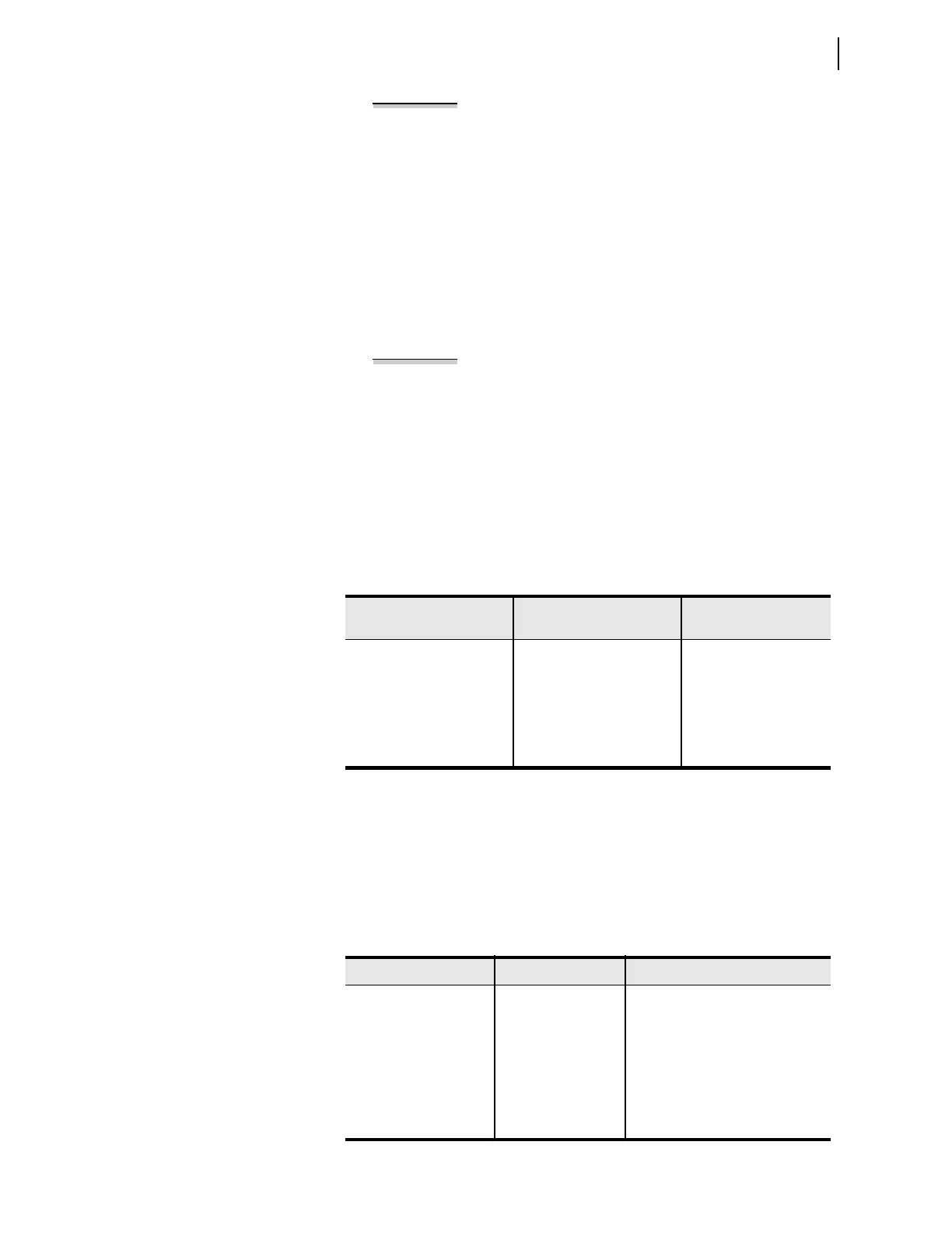
Table 4.68 Setting Group Selection
Setting Prompt Setting Range
Setting Name :=
Fac to ry Defa ult
GRP CHG DELAY 0–400 sec TGR := 3
SELECT GROUP1 SEL
OGIC SS1 := 1
SELECT GROUP2 SEL
OGIC SS2 := 0
SELECT GROUP3 SEL
OGIC SS3 := 0
SELECT GROUP4 SEL
OGIC SS4 := 0
Table 4.69 LEA Ratio and Phase Correction Settings for Phase Voltages
Setting Prompt Setting Range Setting Name := Factory Default
VA RATIO CORRECT 0.500–1.500 VARCF := 1.000
VB RATIO CORRECT 0.500–1.500 VBRCF := 1.000
VC RATIO CORRECT 0.500–1.500 VCRCF := 1.000
VA ANGLE CORRECT –10.0 to 10.0 deg VAPAC := 0.0
VB ANGLE CORRECT –10.0 to 10.0 deg VBPAC := 0.0
VC ANGLE CORRECT –10.0 to 10.0 deg VCPAC := 0.0