4.117
Date Code 20170927 Instruction Manual SEL-751 Relay
Protection and Logic Functions
Group Settings (SET Command)
power element(s) if the power element(s) are still receiving sufficient operat-
ing quantities. Use the power element time delay setting to avoid such race
conditions.
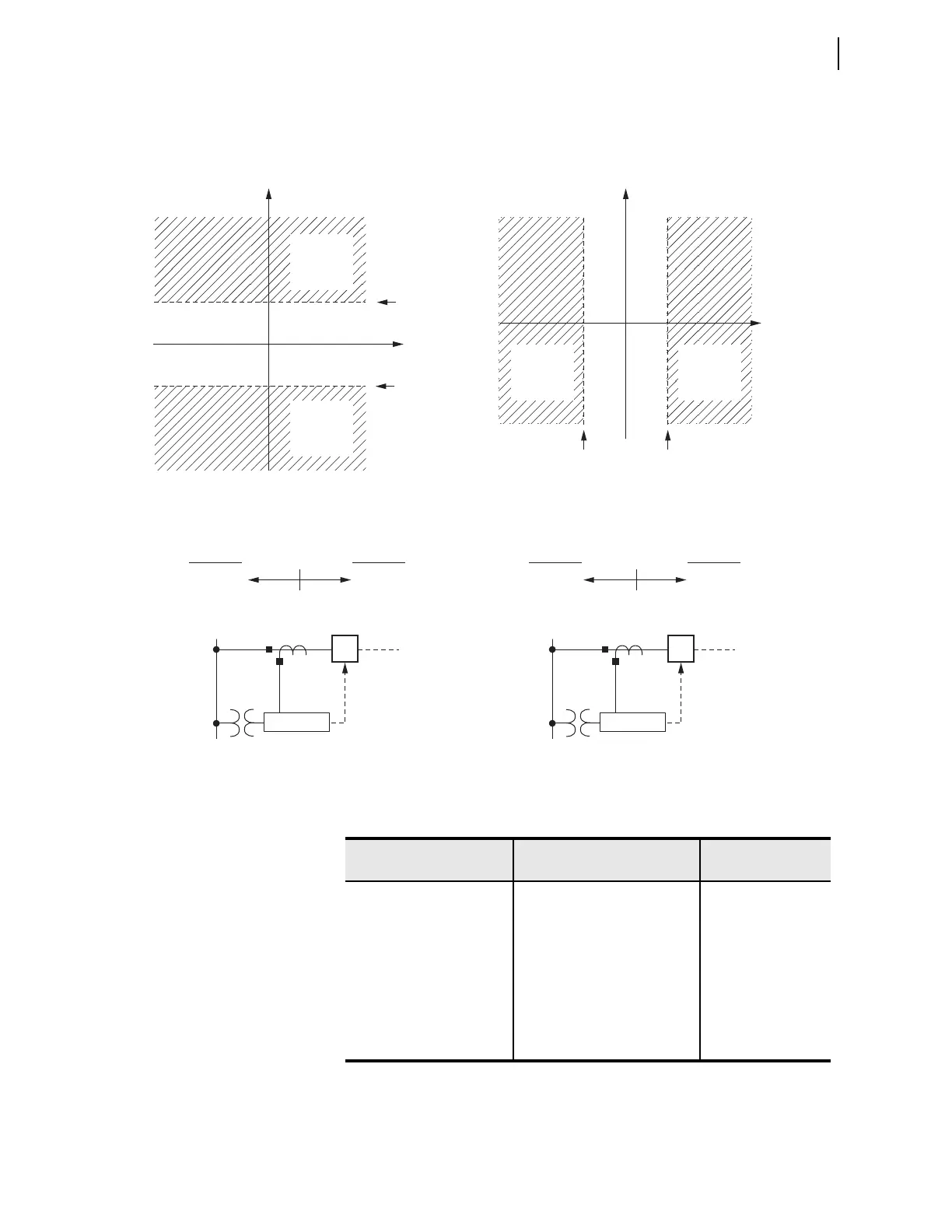
Figure 4.71 Power Elements Operation in the Real/Reactive Power Plane
Power Factor
Elements
If the measured power factor falls below the leading or lagging level for longer
than the time-delay setting, the relay can issue a warning or trip signal. The
power factor elements are enabled 55DLY seconds after Relay Word 52A is
Reactive
Power
Reactive
Power
Real
Power
Real
Power
3PWR2P
(pickup)
3PWR1P
(pickup)
3PWR1P
(pickup)
3PWR2P
(pickup)
Set as Reactive Power Elements
Reverse
(Leading)
3PWR2
3PWR1
3PWR2 3PWR1
Forward
(Lagging)
Set as Real Power Elements
Reverse
Forward
SEL-751
52
SEL-751
52
PWR1T =
+VARS
(type)
PWR2T =
—VARS
(type)
PWR2T =
—WATTS
(type)
PWR1T =
+WATTS
(type)
Note: Highlighted area represents pickup region
Table 4.45 Power Factor Settings
Setting Prompt Setting Range
Setting Name :=
Fac to ry Defa ult
PF LAG TRIP LEVL OFF, 0.05–0.99 55LGTP := OFF
PF LD TRIP LEVEL OFF, 0.05–0.99 55LDTP := OFF
PF TRIP DELAY 1–240 sec 55TD := 1
PF LAG WARN LEVL OFF, 0.05–0.99 55LGAP := OFF
PF LD WARN LEVEL OFF, 0.05–0.99 55LDAP := OFF
PF WARN DELAY 1–240 sec 55AD := 1
PF ARMING DELAY 0–5000 55DLY := 0