4.69
Date Code 20170927 Instruction Manual SEL-751 Relay
Protection and Logic Functions
Group Settings (SET Command)
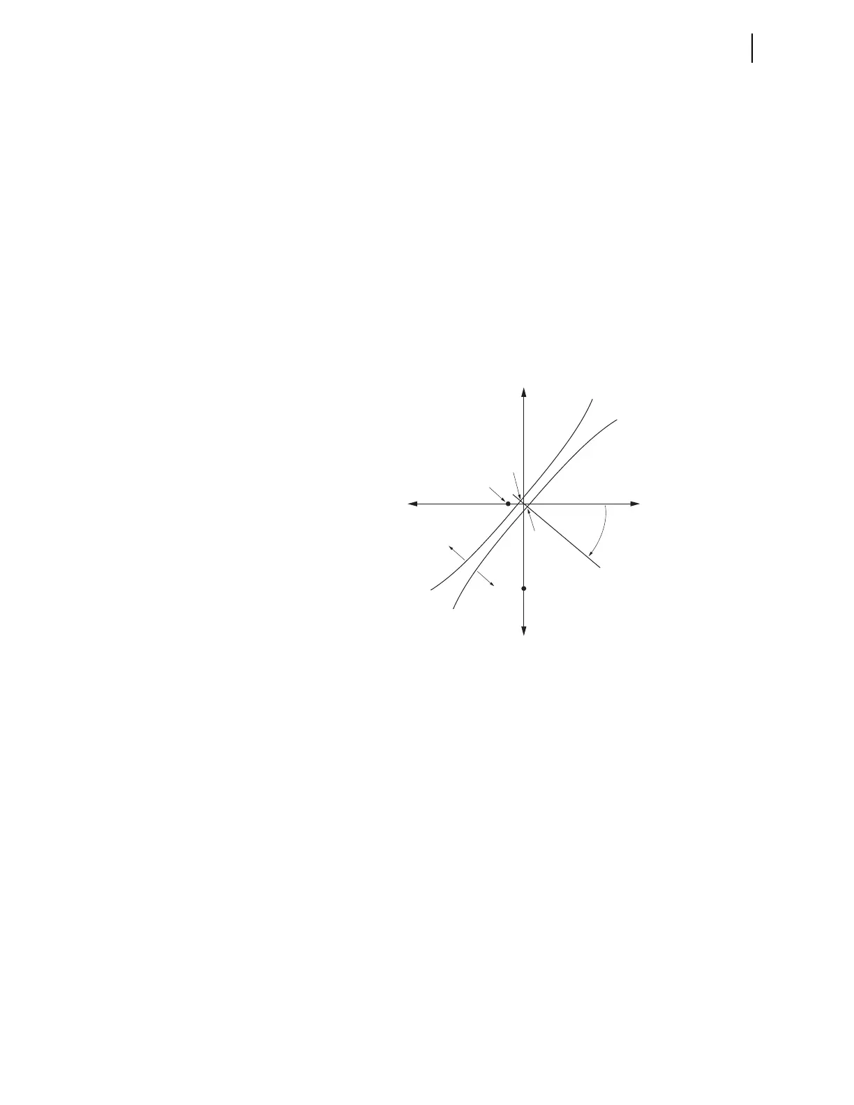
nitely wants to operate for a forward fault. This necessitates a Z0MTA setting
of approximately –40 degrees (for the lowest value of neutral resistance R
G
),
as shown in Figure 4.51 for this example. Necessary settings are as follows:
Group Settings
EDIR := Y
Z0F := —0.05
Z0R := 0.05
Z0MTA := —40.00
Other directional settings also have to be made (see Figure 4.24 and
Figure 4.27).
All these settings, zero-sequence voltage, and zero-sequence current converge
on the zero-sequence voltage-polarized directional element in Figure 4.27
(and its preceding enable logic in Figure 4.24) to produce the directional char-
acteristic in Figure 4.51.
Figure 4.51 Z0MTA Setting Provides Forward/Reverse Ground Fault
Discrimination in a Low-Impedance Grounded Distribution System
For more details on applying the Z0MTA setting on low-impedance grounded
systems, refer to the following technical paper (available at selinc.com):
Selecting Directional Elements for Impedance-Grounded Distribution
Systems by Ronald Lavorin (Southern California Edison), Daqing Hou,
Héctor J. Altuve, Normann Fischer, and Fernando Calero (Schweitzer
Engineering Laboratories, Inc.)
In this paper, especially see pertinent discussion on modified DIRV (zero-
sequence voltage-polarized directional) elements in the following subsections:
➤ V. Modified Directional Elements for Low-Impedance-
Grounded Systems with High Charging Capacitances
➤ VI. Analysis of a Practical Resistance-Grounded System
This subsection includes setting considerations involving the
transformer bank (or grounding bank) zero-sequence
impedance Z
0T
and the neutral resistance R
G
.
R
0
jX
0
Z0R
Z0F
—jX
0
Relay 2
(reverse fault)
Forward
Reverse
Relay 1
(forward fault)
Z0MTA
(negative value)
—R
0