4.101
Date Code 20170927 Instruction Manual SEL-751 Relay
Protection and Logic Functions
Group Settings (SET Command)
Inverse-Time
Undervoltage
Protection
The SEL-751 provides two inverse-time undervoltage protection elements
(27I1 and 27I2). Based on relay hardware options and settings, the 27I ele-
ment offers the flexibility of using various analog quantities as operating
quantities. The availability of these analog quantities is contingent on the set-
tings DELTA_Y, VSCONN, and SINGLEV, as indicated in Tab le 4.36.
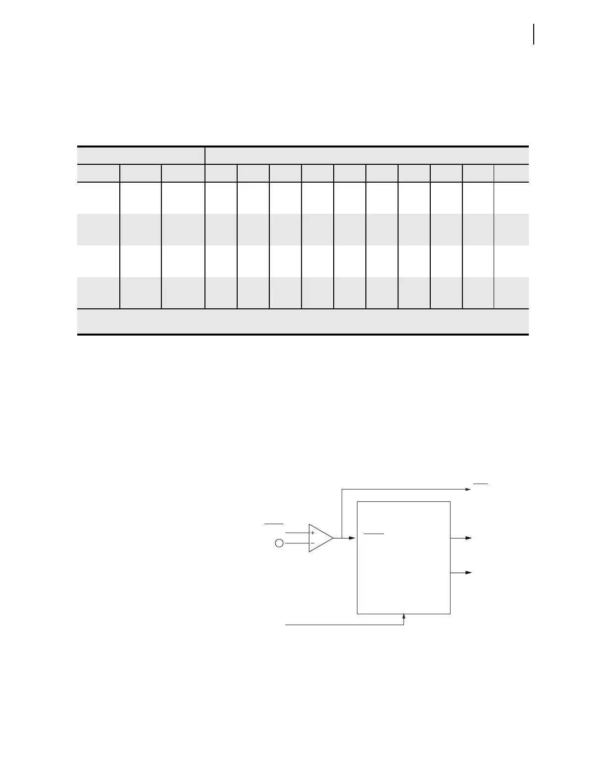
Figure 4.63 shows the inputs, settings and outputs of the inverse-time under-
voltage element.
n = 1 or 2. q Refer to Table 4.36.
Figure 4.63 Logic Diagram of the Inverse-Time Undervoltage Element
When the fundamental frequency component of the operating quantity falls
below the pickup setting (27InP), Relay Word bit 27In asserts. The timer does
not start to integrate unless the operating quantity falls below 0.975 • 27InP.
The inverse-time undervoltage protection element has the characteristic
defined by Equation 4.14.
Table 4.36 Operating Quantities for the 27I Element
Settings Operating Quantities Available in 27InOQ Setting Range
a
DELTA_Y VSCONN SINGLEV VA B VBC VCA VA VB VC V1 VS MINLL MINLN
DELTA 3V0 N ###——— # — # —
DELTA 3V0 Y # ———————— —
DELTA VS N # # # — — — # # # —
DELTA VS Y # — — — — — — # — —
WYE VS N $$$#####$ #
WYE VS Y ——— # ——— # ——
WYE 3V0 N $ $ $ # # # # — $ #
WYE 3V0 Y — — — # — — — — — —
# = 2.00–300.00 V $ = 2.00–520.00 V — Operating quantity is not available
The "#" and "$" signs indicate the setting range for 27InP (n = 1 or 2).
a
The physical meanings of the operating quantities are described as follows:
VAB: Magnitude of A-to-B-phase voltage VC: Magnitude of C-phase voltage
VBC: Magnitude of B-to-C-phase voltage V1: Magnitude of positive-sequence voltage
VCA: Magnitude of C-to-A-phase voltage VS: Magnitude of Vsync voltage
VA: Magnitude of A-phase voltage MINLL: Magnitude of the minimum phase-to-phase voltage
VB: Magnitude of B-phase voltage MINLN: Magnitude of the minimum phase-to-neutral voltage
Settings
Relay
Word
Bits
27I Inverse-Time
Undervoltage Element
Settings
27InP Pick up value
27InCRV Curve selection
27InCFA Coefficient A
27InCFB Coefficient B
27InCFC Coefficient C
27InTD Time dial
27InTTR Time to reset
27InTC Torque control
27In
27InT
27InRS
27InP
27InOQ
27InTC
1