4.21
Date Code 20170927 Instruction Manual SEL-751 Relay
Protection and Logic Functions
Group Settings (SET Command)
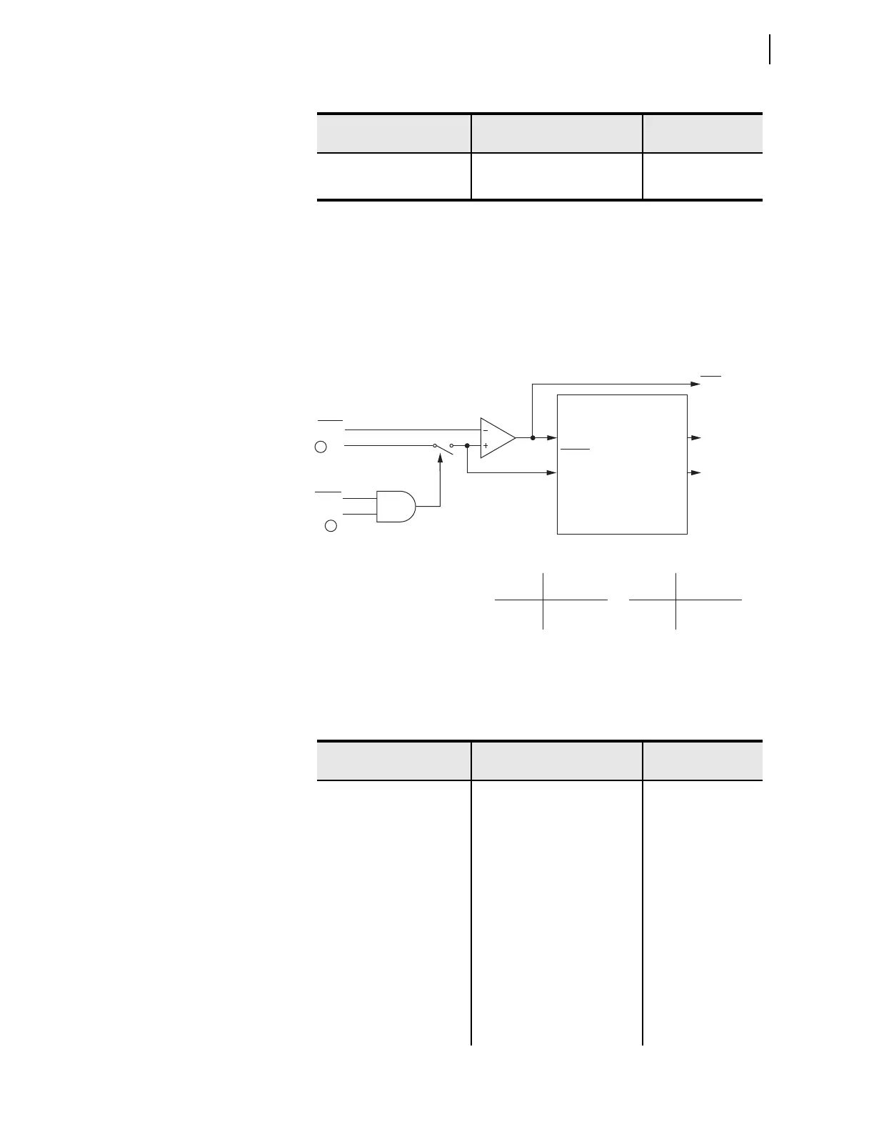
The neutral time-overcurrent elements, 51N1T and 51N2T, respond to neutral
channel current IN as shown Figure 4.8.
n = 1 or 2
q From Figure 4.2; w Figure 4.35
Figure 4.8 Neutral Time-Overcurrent Elements 51N1T and 51N2T
MIN RESPONSE TIM 0.00–1.00 51N2MR := 0.00
TOC TRQ CONTROL SEL
OGIC 51N2TC := 1
a
For I
NOM
= 5 A.
b
For I
NOM
= 1 A.
c
For I
NOM
= 0.2 A.
d
For 51_C := U_.
e
For 51_C := C_.
Table 4.16 Residual Time-Overcurrent Settings (Sheet 1 of 2)
Setting Prompt Setting Range
Setting Name :=
Fac to ry Defa ult
TOC TRIP LVL OFF, 0.25–24.00 A
a
,
0.05–4.80 A
b
51G1P := 0.50
51G1P := 0.10
TOC CURVE SEL U1, U2, U3, U4, U5, C1, C2,
C3, C4, C5
51G1C := U3
TOC TIME DIAL 0.50–15.00
c
,
0.01–1.50
d
51G1TD := 1.50
EM RESET DELAY Y, N 51G1RS := N
CONST TIME ADDER 0.00–1.00 sec 51G1CT := 0.00
MIN RESPONSE TIM 0.00–1.00 51G1MR := 0.00
TOC TRQ CONTROL SEL
OGIC 51G1TC := 1
TOC TRIP LVL OFF, 0.25–24.00 A
a
,
0.05–4.80 A
b
51G2P := 0.50
51G2P := 0.10
TOC CURVE SEL U1, U2, U3, U4, U5, C1, C2,
C3, C4, C5
51G2C := U3
Table 4.15 Neutral Time-Overcurrent Settings (Sheet 2 of 2)
Setting Prompt Setting Range
Setting Name :=
Fac to ry Defa ult
51Nn1P
|IN|
Setting
Torque Control Switch
Pickup
Curve
Timeout
Reset
51Nn1P
51Nn1R
51Nn1T
51Nn1TC Torque Control
State Switch Position
Logical 1 Closed
Logical 0 Open
Setting
51Nn1RS = Reset Timing
Y Electromechanical
N 1 Cycle
Relay
Word
Bits
51Nn1T Neutral
Time-Overcurrent Element
Curve Timing and Reset Timing
Settings
51Nn1P Pickup
51Nn1C Curve Type
51Nn1TD Time Dial
51Nn1RS Electromechanical
Reset? (Y/N)
51Nn1CT Const. Time Add.
51Nn1MR Min. Response
Controls the Torque Control Switch
1
51NnTC
Torque
Control
SEL
OGIC
Setting
N1DIR
2