9.2
SEL-751 Relay Instruction Manual Date Code 20170927
Bay Control
Overview
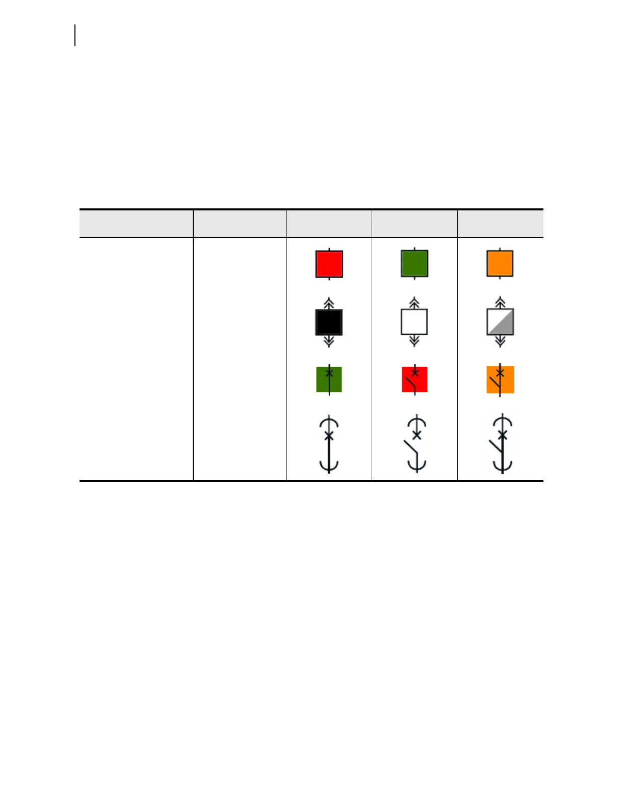
Table 9.1 provides typical ANSI and IEC breaker symbols that are supported
by Bay Screen Builder. Column 1 identifies the standard (ANSI/IEC) and the
type of breaker. Columns 3, 4, and 5 identify closed, open, and alarm states of
the breaker image, respectively. Bay Screen Builder allows you to set the
breaker color sequence property (identified in Column 2) for each of these
states. Select the breaker color sequence based on your system convention.
For a complete list of ANSI and IEC circuit breaker symbols available to use
with the bay screens, refer to the
ACSELERATOR Bay Screen Builder SEL-5036
Software Instruction Manual, available in the Help > Contents menu of Bay
Screen Builder.
Disconnect Switch
Symbol Settings and
Status Logic
The SEL-751 supports as many as five monitor-only two-position disconnect
switches. The relay firmware does not support the control logic to open and
close the disconnects. The disconnect control logic can be programmed with
SEL
OGIC control equations in conjunction with front-panel pushbuttons. Refer
to Table 9.2 for the disconnect settings. The 89A2Pn and 89B2Pn (n =1, 2, 3,
4, or 5) SEL
OGIC control equation settings represent the normally open and
normally closed disconnect auxiliary contacts. Typically, these SEL
OGIC
control equation settings are set to SEL-751 inputs that are wired to the
corresponding auxiliary contacts. Figure 9.1 shows the dual-point disconnect
status logic. The Relay Word bits 89CL2Pn and 89OP2Pn indicate the
disconnect switch closed and open states, respectively. 89AL2Pn indicates the
alarm status of the disconnect and asserts when the disconnect switch is in an
undetermined state for longer than the 89A2PnD timer. Set the 89A2PnD
timer longer than the expected operation time (undetermined state). Refer to
Table 9.5 for the Bay Control disconnect switch settings. Refer to Bay
Control Application Example on page 9.13 for example settings.
Ta b l e 9.1 Circu i t Br e a ke r Sym b o l s
Type
Breaker Color
Sequence
State 1 (Closed) State 2 (Open) State 3 (Alarm)
ANSI Breaker Red, Green, Amber
ANSI Truck Operated Breaker Black, White, Grey
IEC Breaker Green, Red, Amber
IEC Truck Operated Breaker Transparent