4.22
SEL-751 Relay Instruction Manual Date Code 20170927
Protection and Logic Functions
Group Settings (SET Command)
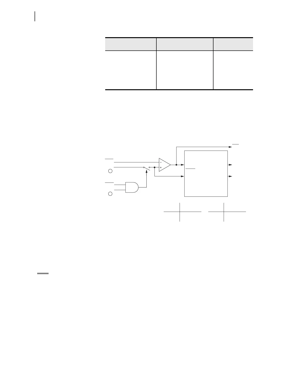
The residual time-overcurrent elements, 51G1T and 51G2T, respond to
residual current IG as shown in Figure 4.9.
n = 1 or 2
q From Figure 4.2; w From Figure 4.34
Figure 4.9 Residual Time-Overcurrent Elements 51G1T and 51G2T
Time-Overcurrent Curves
The following information describes the curve timing for the curve and time
dial settings made for the time-overcurrent elements (see Figure 4.5 through
Figure 4.9). The U.S. and IEC time-overcurrent relay curves are shown in
Figure 4.10 through Figure 4.19. Curves U1, U2, and U3 (Figure 4.10 through
Figure 4.12) conform to IEEE C37.112-1996 IEEE Standard Inverse-Time
Characteristic Equations for Overcurrent Relays.
TOC TIME DIAL 0.50–15.00
c
,
0.01–1.50
d
51G2TD := 1.50
EM RESET DELAY Y, N 51G2RS := N
CONST TIME ADDER 0.00–1.00 sec 51G2CT := 0.00
MIN RESPONSE TIM 0.00–1.00 51G2MR := 0.00
TOC TRQ CONTROL SEL
OGIC 51G2TC := 1
a
For I
NOM
= 5 A.
b
For I
NOM
= 1 A.
c
For 51_C := U_.
d
For 51_C := C_.
Table 4.16 Residual Time-Overcurrent Settings (Sheet 2 of 2)
Setting Prompt Setting Range
Setting Name :=
Fac to ry Defa ult
51GnP
Setting
51GnTC
Torque Control Switch
Torque
Control
Pickup
51GnP
Reset
51GnR
Curve
Timeout
51GnT
Torque
Control Torque Control
State Switch Position
Logical 1 Closed
Logical 0 Open
Setting
51GnRS= Reset Timing
Y Electromechanical
N 1 Cycle
Relay
Word
Bits
SEL
OGIC
Setting
51GnT Residual
Time-Overcurrent Element
Curve Timing and Reset Timing
Settings
51GnP Pickup
51GnC Curve Tpe
51GnTD Time Dial
51GnRS Electromechanical
Reset? (Y/N)
51GnCT Const. Time Add.
51GnMR Min. Response
|IG|
1
G1DIR
2
NOTE: The time-overcurrent curves
in Figure 4.10 through Figure 4.19
show operating times flattening at
M = 30 (30 multiples of pickup). This
is true for the overcurrent pickup set
equal to the CT nominal rating (I
NOM
)
and no significant dc offset. The
flattening may start at different
points depending on the actual
pickup setting, e.g., if pickup is
4.8 • I
NOM
, the curve starts flattening
at M = 30/4.8 = 6.25.