I.3
Date Code 20170927 Instruction Manual SEL-751 Relay
Synchrophasors
Synchrophasor Measurement
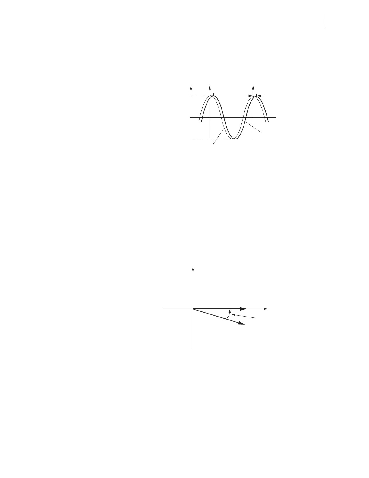
VSCOMP, and ICOMP, entered in degrees, are added to the measured phasor
angles to create the corrected phasor angles, as shown in Figure I.2,
Figure I.3, and Equation I.1. The VCOMP, VSCOMP, and ICOMP settings
can be positive or negative values. The corrected angles are displayed in the
MET PM command and transmitted as part of synchrophasor messages.
Figure I.2 Waveform at Relay Terminals May Have a Phase Shift
Equation I.1
If the time shift on the PT measurement path t
pt
= 0.784 ms and the nominal
frequency, freq
nominal
= 60Hz, use Equation I.2 to obtain the correction angle:
Equation I.2
Figure I.3 Correction of Measured Phase Angle
The phasors are rms values scaled in primary units, as determined by Group
settings PTR, PTRS (for synchronism-check input), CTR, and CTRN.
Because the sampling reference is based on the GPS clock (IRIG-B signal)
and not synchronized to the power system, an examination of successive
synchrophasor data sets almost always shows some angular change between
samples of the same signal. This is not a malfunction of the relay or the power
system, but is merely a result of viewing data from one system with an
instrument with an independent time base. In other words, a power system has
a nominal frequency of either 50 or 60 Hz, but on closer examination, it is
usually running a little faster or slower than nominal.
94.851
–94.851
Δt
pt
0
t
V
A
(t)
Actual
Waveform
Measured
Waveform
Compensation Angle
t
pt
1
freq
nominal
----------------------------
---------------------------------- 360• =
t
pt
freq
nominal
360• • =
0.784 10
3–
s60s
1–
360• • • 16.934=
Imaginary
Real
M
M
V
A measured
V
A corrected
Compensation Angle