4.107
Date Code 20170927 Instruction Manual SEL-751 Relay
Protection and Logic Functions
Group Settings (SET Command)
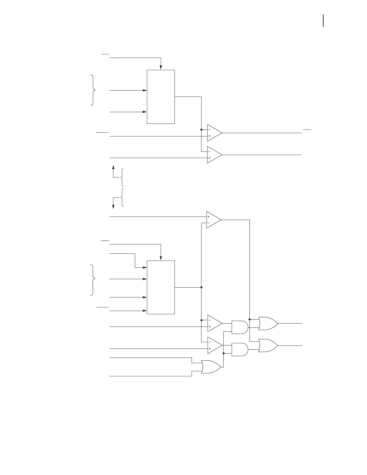
q From Figure 4.67; w see Figure 4.81.
Figure 4.68 Synchronism-Check Elements
These synchronism-check elements are explained in detail in the following
text.
Angle
Difference
Calculator
Angle
Difference
Calculator
Slip Frequency Element
Maximum Angle 1
Maximum Angle 2
Maximum Angle 1
Breaker Close Time
Maximum Angle 2
Slip Frequency Element
SF
VP
VP
VS
VS
Relay
Word
Bits
SF
Slip
Frequency
q
0°
Relay
Word
Bits
25A1
25A2
25A1
25A2
Relay
Word
Bits
Angle
Difference
Angle
Difference
(absolute value)
(absolute value–
compensated by
setting TCLOSD)
Synchronism-Check Element 1
Synchronism-Check Element 2
Synchronize at
Angle Difference = 0°
Operation of Synchronism-Check Elements if voltages VP
and VS are static (not slipping):
slip frequency ≤ 0.005 Hz or:
Setting TCLOSD = OFF
Operation of Synchronism-Check Elements if voltages VP
and VS are slipping:
0.005 Hz < slip frequency ≤ setting 25SF and:
Setting TCLOSD ≠ OFF
25ANG1
25ANG2
Settings
TCLOSD
25ANG1
25ANG2
Angle
Difference Increasing
Last Check of
SEL
OGIC Setting
79CLS (w)
Settings
Synchronism-
Check
Element 1
Synchronism-
Check
Element 2
VP = 25RCF*VPH
where VPH = VA, VB, VC,
VAB, VBC, or VCA,
depending on the
SYNCPH setting.
VP = 25RCF*VPH
where VPH = VA, VB, VC,
VAB, VBC, or VCA
depending on
the SYNCPH setting.