2.17
Date Code 20170927 Instruction Manual SEL-751 Relay
Installation
I/O Configuration
Analog Input Card
Voltage/Current
Jumper Selection
Figure 2.3 shows the circuit board of an analog I/O board. Jumper x (x = 1–8)
determines the nature of each channel. For a current channel, insert Jumper x
in position 1–2; for a voltage channel, insert Jumper x in position 2–3.
Figure 2.3 Circuit Board of Analog I/O Board, Showing Jumper Selection
Analog Output (AO)
Configuration Jumper
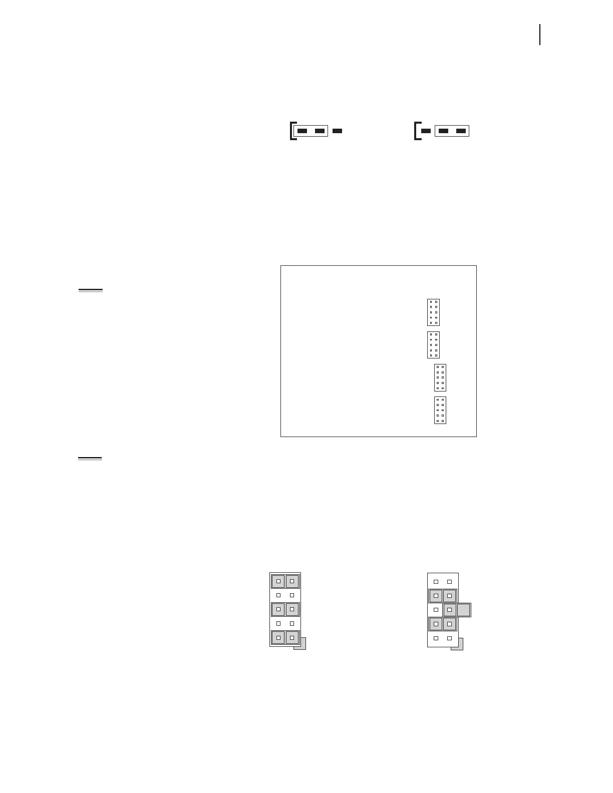
Figure 2.4 shows the locations of JMP1 through JMP4 on an analog output
board. You can select each of the four analog output channels as either a
current analog output or a voltage analog output.
Figure 2.4 JMP1 Through JMP4 Locations on 4 AI/4 AO Board
NOTE:
There is no jumper between
pins 5 and 6 for a voltage analog
output selection.
You need to insert three jumpers for a current analog output selection and two
jumpers for a voltage analog output selection. For a current analog output
selection, insert a jumper between Pins 1 and 2, Pins 5 and 6, and Pins 9 and
10. For a voltage analog output selection, insert a jumper between Pins 3
and 4, and Pins 7 and 8. Figure 2.5 shows JMP4 selected as a current analog
output. The current analog output selection is the default setting for JMP1
through JMP4. Figure 2.6 shows JMP1 selected as a voltage analog output.
JMPX
213 213
JMPX
Position 2 – 3 = V (voltage) mode
Where "JMPX" is the jumper for AI channel "X"
Position 1 – 2 = I (current) mode
(default position)
9
7
5
3
1
10
8
6
4
2
JMP1
9
7
5
3
1
10
8
6
4
2
JMP2
9
7
5
3
1
10
8
6
4
2
JMP3
9
7
5
3
1
10
8
6
4
2
JMP4
NOTE: Analog inputs cannot provide
loop power. Each analog output is self
powered and has an isolated power
supply.
Figure 2.5 Current Output Jumpers Figure 2.6 Voltage Output Jumpers
9
5
1
10
6
2
JMP4
JMP4 Selected as Current Output
7
5
3
8
6
4
JMP1
JMP1 Selected as Voltage Output