4.194
SEL-751 Relay Instruction Manual Date Code 20170927
Protection and Logic Functions
Front-Panel Settings (SET F Command)
configure bay screens with analog and digital labels, similar to the display
point functionality in the two-line display model. Refer to Section 9: Bay Con-
trol for the procedure to create configurable bay screens.
To optimize the time you spend on setting the device, only the number of
enabled display points and enabled local bits become available for use. Use
the front-panel LCD timeout setting FP_TO as a security measure. If the dis-
play is within an Access Level 2 function when a timeout occurs, such as the
device setting entry, the function is automatically terminated (without saving
changes) after inactivity for this length of time. After terminating the function,
the front-panel display returns to the default display. The FP_TO setting is not
available in the touchscreen display model. Refer to Section 9: Bay Control
for the touchscreen display settings.
If you prefer to disable the front-panel timeout function during device testing,
set the LCD timeout equal to OFF. Use the front-panel LCD contrast setting
FP_CONT to adjust the contrast of the liquid crystal display. The FP_CONT
setting is not available in the touchscreen display model. Use the front-panel
auto-message setting FP_AUTO to define displaying of Trip/Warning mes-
sage. Set FP_AUTO either to OVERRIDE or add to the Rotating display when
the relay triggers a Trip/Warning message. Refer to Table 9 .5 for the equiva-
lent touchscreen display settings. Note that the FP_AUTO setting is not avail-
able in the touchscreen display model. The touchscreen display provides
settings that allow you to choose from a wide range of screens, including cus-
tom screens, that can be displayed as part of the rotating display. The touch-
screen automatically flashes a screen overriding the rotating display in the
case of trip or diagnostic failures. Refer to Section 8: Front-Panel Operations
for more information on trip and diagnostic messages. Set RSTLED := Y to
reset the latched LEDs automatically when the breaker or contactor closes.
The MAXACC setting (under Front-Panel Settings) selects the highest access
level for the front-panel. If MAXACC is set to 1, the front panel only allows
metering and read access to settings. If MAXACC is set to 2, the front panel
allows breaker control and read/write access to settings.
Table 4.90 Display Point and Local Bit Default Settings
Setting Setting Prompt Range Default
EDP
a
a
The setting EDP is not supported in the touchscreen display model.
DISPLAY PTS ENABL N, 1–32 4
ELB LOCAL BITS ENABL N, 1–32 N
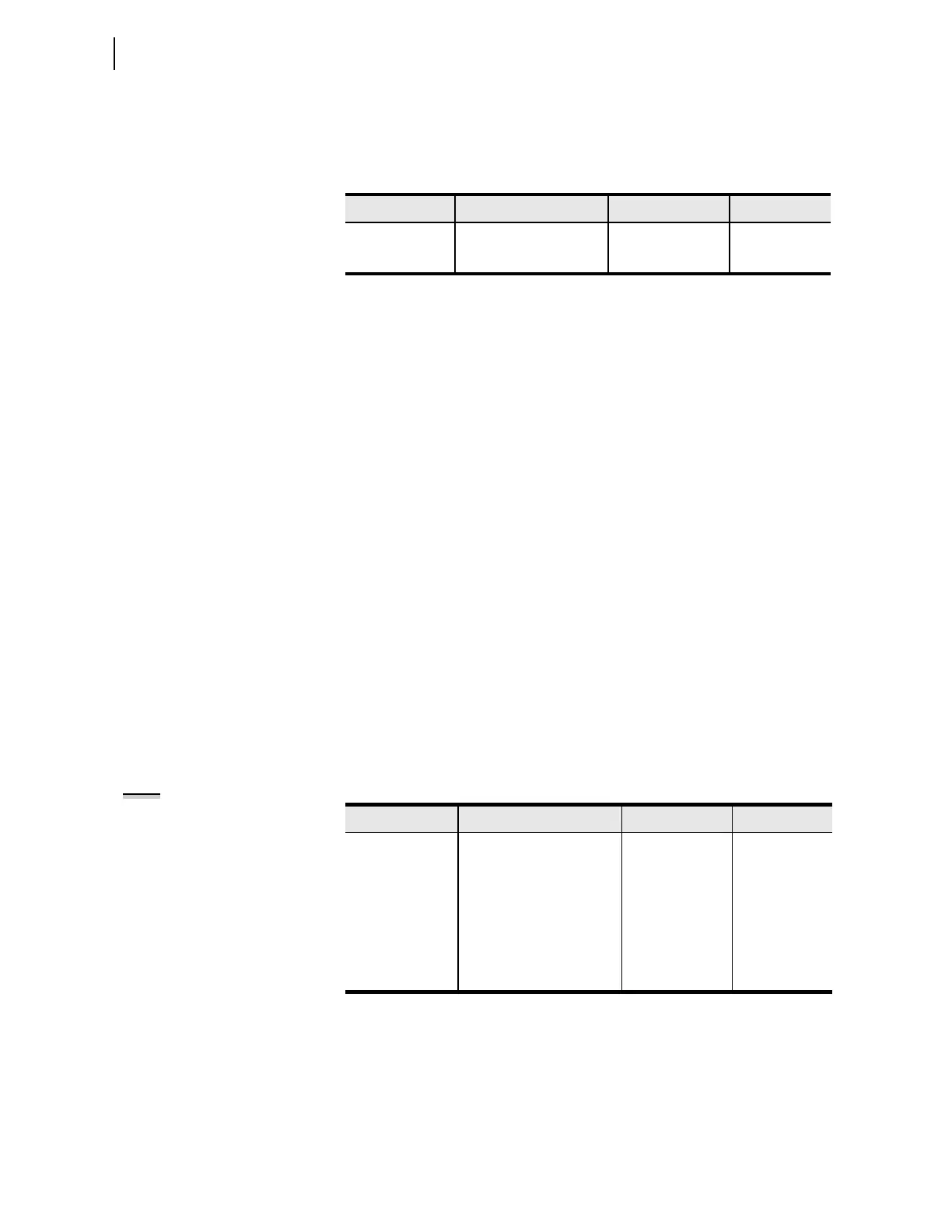
Table 4.91 LCD Display Settings
Setting Setting Prompt Range Default
FP_TO
a
a
The settings FP_TO, FP_CONT, FP_AUTO, and MAXACC are not supported in the touchscreen
display model.
LCD TIMEOUT OFF, 1–30; min 15
FP_CONT
a
LCD CONTRAST 1–16 10
FP_AUTO
a
FP AUTOMESSAGES OVERRIDE,
ROTATING
OVERRIDE
RSTLED CLOSE RESET LEDS Y, N Y
MAXACC
a
MAXIMUM ACCESS
LEVEL
1, 2 2
NOTE: All Target LED settings can
be found in Table 4.98