4.116
SEL-751 Relay Instruction Manual Date Code 20170927
Protection and Logic Functions
Group Settings (SET Command)
EPWR := 3P1 enables one three-phase power element. Set EPWR := 3P2 if
you want to use both elements.
Set the element pickup, 3PH PWR ELEM PU, to the values you want.
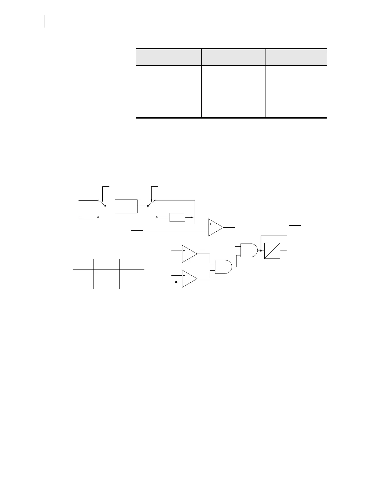
Figure 4.70 shows the power element logic diagram and Figure 4.71 shows
the operation in the Real/Reactive power plane.
Figure 4.70 Three-Phase Power Elements Logic
The power element type settings are made in reference to the load convention:
➤ +WATTS: positive or forward real power
➤ –WATTS: negative or reverse real power
➤ +VARS: positive or forward reactive power
➤ –VARS: negative or reverse reactive power
The two power element time delay settings, PWR1D and PWR2D, can be set
to have no intentional delay for testing purposes. For protection applications
involving the power element Relay Word bits, SEL recommends a minimum
time delay setting of 0.1 second for general applications. The classical power
calculation is a product of voltage and current, to determine the real and reac-
tive power quantities. During a system disturbance, because of the high sensi-
tivity of the power elements, the changing system phase angles and/or
frequency shifts may cause transient errors in the power calculation.
The power elements are not supervised by any relay elements other than the
minimum voltage check shown in Figure 4.70. If the protection application
requires overcurrent protection in addition to the power elements, there may
be a race condition, during a fault, between the overcurrent element(s) and the
PWR ELEM DELAY 0.0–240.0 s PWR1D := 0.0
3PH PWR ELEM PU OFF, 1.0–6500.0 VA
a
(sec-
ondary)
3PWR2P := OFF
PWR ELEM TYPE +WATTS, –WATTS,
+VARS, –VARS
PWR2T := +VARS
PWR ELEM DELAY 0.0–240.0 s PWR2D := 0.0
a
The range shown is for 5 A input; range for 1 A input is OFF, 0.2—1300.0 VA.
Table 4.44 Power Element Settings (Sheet 2 of 2)
Setting Prompt Setting Range
Setting Name :=
Fac to ry Defa ult
PWRnD
0
|V
AB
|
20 V
3PWRnT
Relay
Word
Bits
Switch A
Position
+WATTS
–WATTS
+VARS
–VARS
Setting
PWRnT
1
1
2
2
Switch B
Position
1
2
1
2
Where n = 1 or 2
2 Cycle
Average
•(–1)
Switch A Switch B
11
22
3PWRnP
|V
BC
|
3PWRnP
Setting
P
Q
* lVBCl = lVABl if setting SINGLEV := Y
*