4.129
Date Code 20170927 Instruction Manual SEL-751 Relay
Protection and Logic Functions
Group Settings (SET Command)
NOTE: The factory-default
assignment of the Relay Word bit TRIP
is the output OUT103. See Table 4.65
for the output contacts settings.
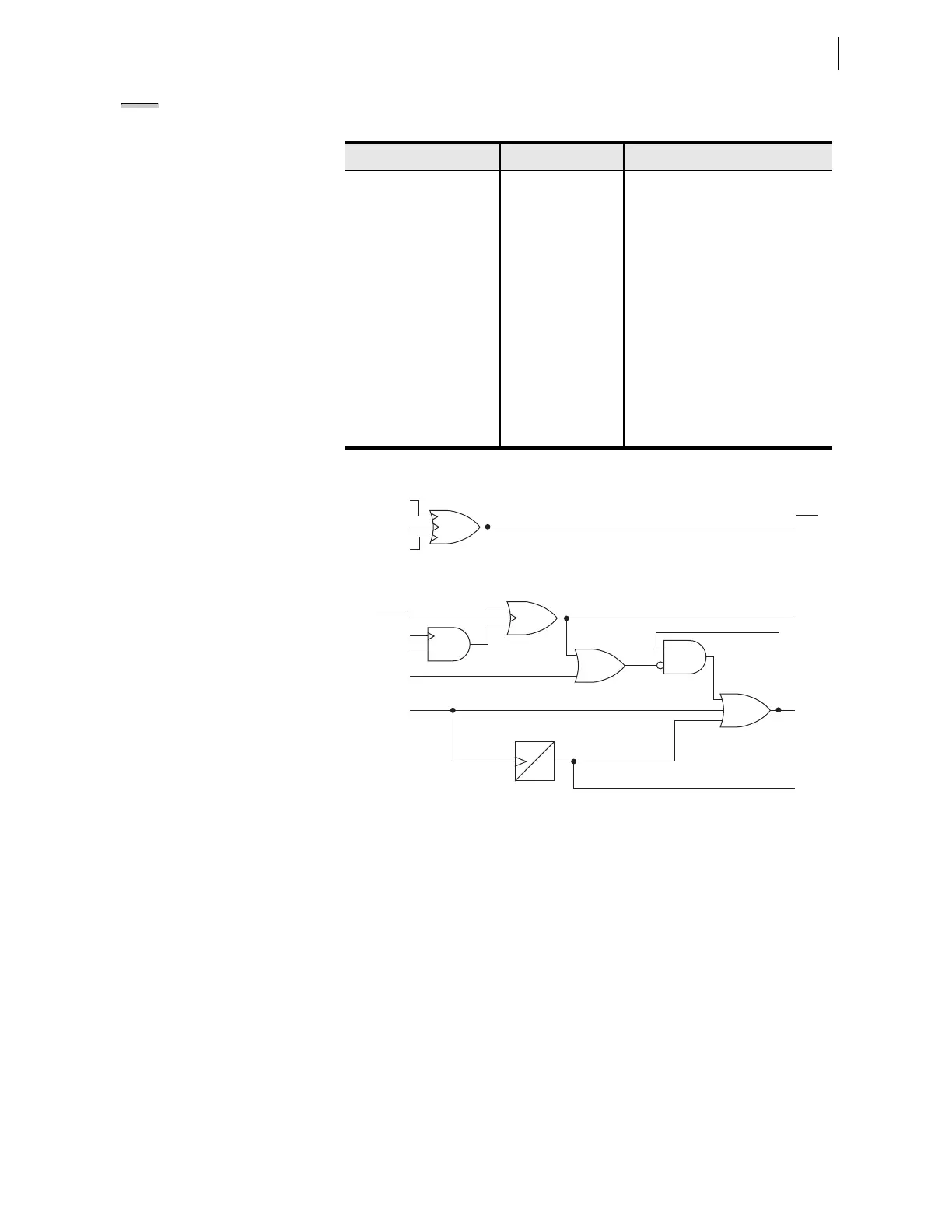
Figure 4.79 Trip Logic
The trip logic settings, including the SELOGIC control equations, are described
in the following text.
TDURD Minimum Trip Time
This timer establishes the minimum time duration for which the TRIP Relay
Word bit asserts. This is a rising-edge initiated timer.
Trips initiated by the TR Relay Word bit (includes OPEN command from
front-panel and serial ports) are maintained for at least the duration of the min-
imum trip duration time (TDURD) setting.
TR Trip Conditions SELOGIC Control Equation
The SEL-751 TR SELOGIC control equation provides the trip logic to trip the
breaker. The Relay Word bit TRIP is associated with the TR SEL
OGIC control
equation.
Table 4.52 Trip/Close Logic Settings
Setting Prompt Setting Range Setting Name := Factory Default
MIN TRIP TIME 0.0–400.0 sec TDURD := 0.5
CLOSE FAIL DLY OFF, 0.0–400.0 sec CFD := 1.0
TRIP EQUATION SV TR := ORED50T OR ORED51T OR
ORED81T OR REMTRIP OR OC
OR SV04T
REMOTE TRIP EQN SV REMTRIP := 0
UNLATCH TRIP SV ULTRIP := NOT (51P1P OR 51G1P
OR 51N1P OR 52A)
BRKR N/O CONT SV 52A := 0
BRKR N/C CONT SV 52B := NOT 52A
CLOSE EQUATION SV CL := SV03T AND LT02 OR CC
UNLATCH CLOSE SV ULCL := 0
0
TDURD
Serial Port
Command TAR R
TARGET RESET
Pushbutton
TRGTR
Reset
TRIP LED
TRIP
Trigger
Events
Unlatch
Trip
Trips
Comm.
Target Reset
RSTTRGT
ULTRIP
TR
52A
RSTLED = Y
Relay
Word
Bits
SELOGIC
Settings