2.2
SEL-751 Relay Instruction Manual Date Code 20170927
Installation
I/O Configuration
Relay Mounting
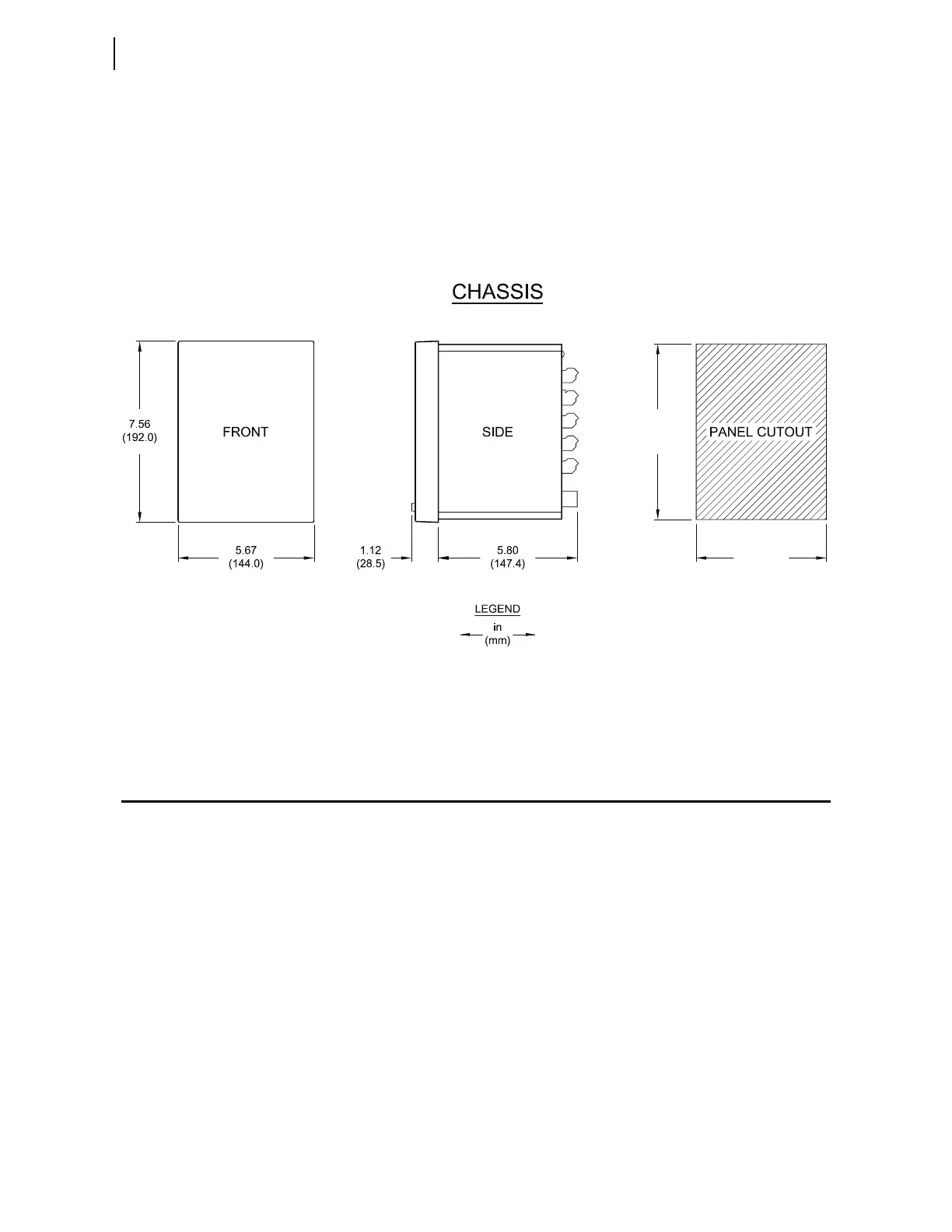
To flush mount the SEL-751 in a panel, cut a rectangular hole with the dimen-
sions shown in Figure 2.1. Use the supplied front-panel gasket for protection
against dust and water ingress into the panel. The relay is rated IP65 when the
two-line display model is enclosed in a panel and rated IP54 when the touch-
screen display model is enclosed in a panel. For extremely dusty environ-
ments, use the optional IP50-rated terminal dust-protection assembly
(protection against solid foreign objects only) (SEL Part 915900170).
A 10°C-temperature derating applies to the temperature specifications of the
relay when using Part 915900170.
Figure 2.1 Relay Panel-Mount Dimensions
Refer to Section 1: Introduction and Specifications, Models, Options, and
Accessories on page 1.5 for information on mounting accessories.
I/O Configuration
Your SEL-751 offers flexibility in tailoring I/O to your specific application. In
total, the SEL-751 has six rear-panel slots, labeled as Slots A, B, C, D, E, and Z.
Slots A, B, and Z are base unit slots, each associated with a specific function.
Optional digital/analog I/O, communications, RTD, and voltage cards are
available for the SEL-751. Figure 2.2 shows the slot allocations for the cards.
Because installations differ substantially, the SEL-751 offers a variety of card
configurations to provide options for the many diverse applications. Choose
the combination of option cards most suited for your application from the fol-
lowing selection.
7.36
(187.0)
5.47
(139.0)
i9089b