4.73
Date Code 20170927 Instruction Manual SEL-751 Relay
Protection and Logic Functions
Group Settings (SET Command)
Real (3V
0
• conjugate [3I
0
]) = |3V
0
| • |3I
0
| • cos(3V
0
– 3I
0
) =
|3V
0
|•|I
N
| • cos(3V
0
– I
N
)
The cosine part of the previous calculation reveals forward or reverse fault
direction: forward faults produce negative calculation values and reverse faults
produce positive calculation values on Petersen coil-grounded systems. Calcu-
late the DIRWFP and DIRWRP wattmetric pickup settings (in watts second-
ary), with a margin of more sensitivity than the minimum detected ground
faults (forward and reverse, respectively). Enter wattmetric settings as positive
values.
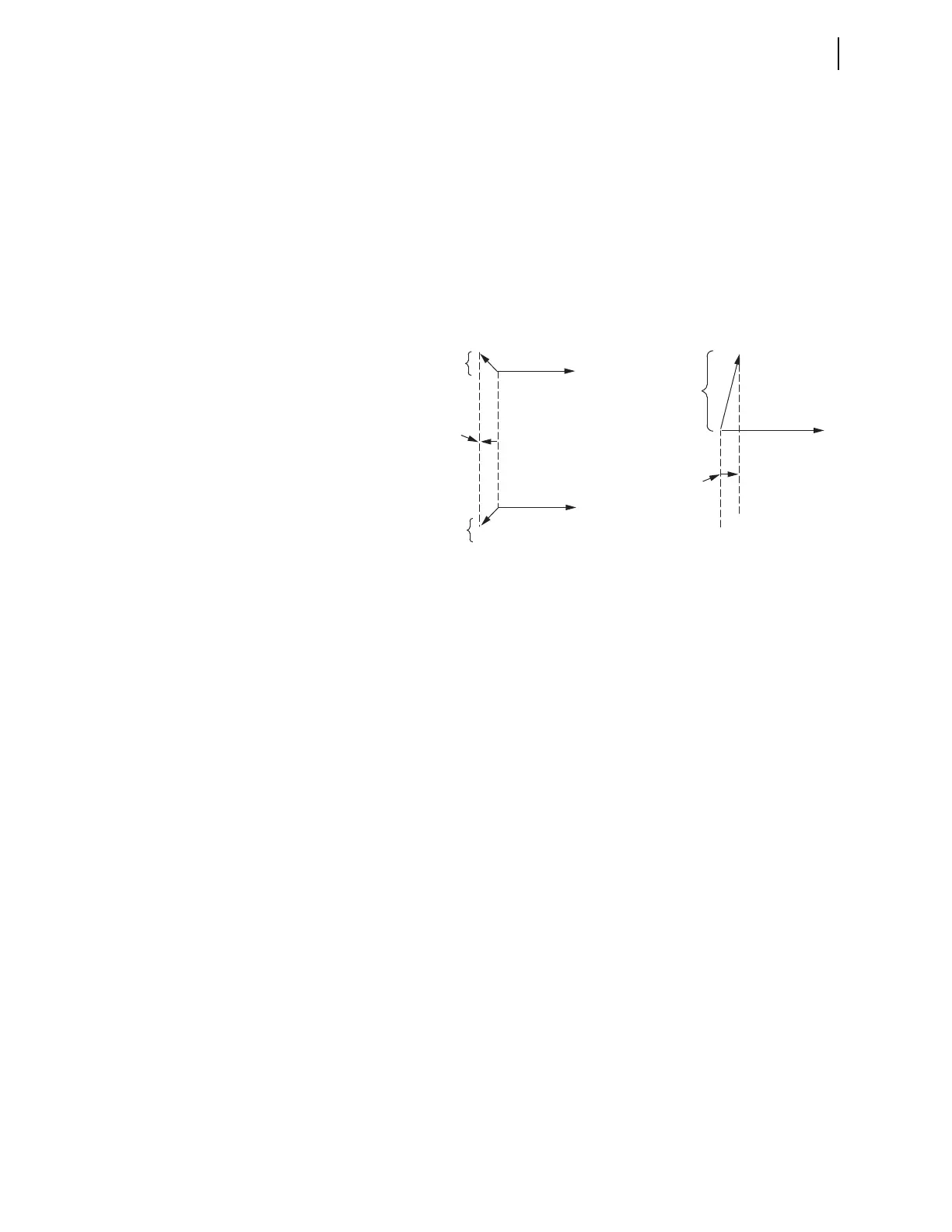
Figure 4.53 Wattmetric Element Operation for Ground Fault on Feeder 1
The sum of settings DIRWFP and DIRWRP must be 0.1 watts secondary or
greater:
DIRWFP + DIRWRP 0.1 watts secondary
In Figure 4.53, the calculated wattmetric value for a forward fault is a negative
value (shown as WF), while that for a reverse fault is a positive value (shown
as WR). Again, corresponding settings DIRWFP and DIRWRP are both
entered as positive values, with some margin of sensitivity. The above
“0.1 watts secondary” rule is effectively the minimum distance between set-
tings DIRWFP and DIRWRP in the wattmetric plane (setting DIRWFP is put
on the “negative” side of the wattmetric plane: i.e., “–DIRWFP”; see
Figure 4.30).
DIRWD—Wattmetric Delay (Petersen Coil-Grounded System)
If setting ORDER does not contain P (Petersen coil directional element is not
enabled) or the model does not have a 0.2 A nominal neutral channel (IN), then
setting DIRWD is not made or displayed.
Settings Considerations for Petersen Coil-Grounded Systems
The Petersen coil elements require a zero-sequence voltage source, which is
calculated from voltages V
A
, V
B
, and V
C
when the relay is wye connected
(DELTA_Y:= WYE and VSCONN := VS), or which is measured from the VS
channel when the relay is connected to a broken-delta 3V
0
source and
VSCONN := 3V0. Three of the required Petersen coil element settings,
59RES, DIRWFP, and DIRWRP, depend on the type of 3V
0
voltage source
and on the PTR and PTRS group settings.
Net capacitive behind
Relay 1 (under-
compensated system)
Relay 1 / Faulted Feeder 1
Calculated "negative"
wattmetric value
(forward fault)
Net inductive behind
Relay 1 (tuned or over-
compensated system)
0
V
0
V
0
V
I
0(1)
I
0(1)
Calculated "positive"
wattmetric value
(reverse fault)
Capacitive in
front of Relay 2
I
0(2)
Relay 2 / Unfaulted Feeder 2
WF
WR