4.72
SEL-751 Relay Instruction Manual Date Code 20170927
Protection and Logic Functions
Group Settings (SET Command)
tem). In such an optimum tuned state, little current flows through the Petersen
coil. Some Petersen coils are continually adjusted automatically, as load lev-
els/system topology change, so that tuning remains optimum. The “tuned cir-
cuit” resists sustaining an arc, so many ground faults are self-extinguished by
the circuit itself (no circuit breaker operation necessary).
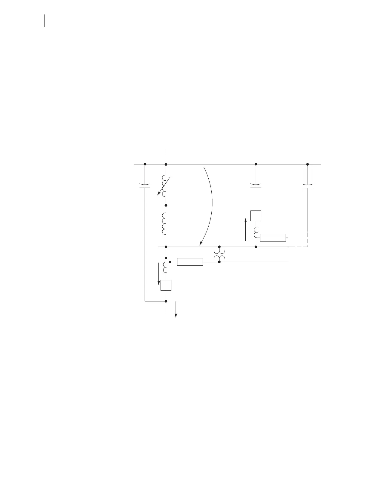
Consider a permanent line-to-ground fault out on the feeder in Figure 2.30
(refer to the relay and feeder shown in Figure 2.30 as Relay 1 and Feeder 1,
respectively; other feeders on the same bus, though not shown in Figure 2.30,
are then Relay 2/Feeder 2, etc.). In the zero-sequence network view in
Figure 4.52, Relay 2 (on unfaulted Feeder 2) sees mostly capacitance in front
of it. Assuming a “tuned circuit,” I
0
= 0 at the fault. Thus, the entire zero-
sequence capacitance shown in Figure 4.52 is canceled out by the inductance
of the Petersen coil. So, with Feeder 1 capacitance C
1
in front of Relay 1, the
system behind Relay 1 appears net inductive.
Figure 4.52 Zero-Sequence Impedance Network for Ground Fault on Feeder 1
Figure 4.53 shows the zero-sequence vector relationships described above for
Figure 4.52 (note: the zero-sequence currents I
0(1)
and I
0(2)
are what the relays
respectively “see,” per standard current transformer connections—see
Figure 2.30). The vectors shown in Figure 4.53 are perhaps somewhat over-
dramatic as far as angle differences—they are primarily for illustrative pur-
poses.
There is always some resistance in a circuit and thus the V
0
and I
0
vector rela-
tionship is not 90 degrees, as shown in Figure 4.53. This system resistance
provides the “real power component” with which the wattmetric directional
element (Figure 4.30) operates. Whether the zero-sequence network behind
Relay 1 appears net capacitive or net inductive, the wattmetric (real power)
portion for Relay 1/faulted Feeder 1 (labeled “WF”) is polar-opposite of the
wattmetric (real power) portion for Relay 2/unfaulted Feeder 2 (labeled
“WR”). The calculations for the DIRWFP and DIRWRP wattmetric pickups
are made as follows:
Petersen
Coil
Transformer
Bank
C
1
C
2
C
n
Feeder 2
Feeder n
Relay 1
V
0
2
Relay 2
I
0(2)
1
I
0(1)
Feeder 1
I
0
= 0 (Tuned System)
Zero-Sequence Reference Bus