4.50
SEL-751 Relay Instruction Manual Date Code 20170927
Protection and Logic Functions
Group Settings (SET Command)
NOTE: When SINGLEV = Y, Group
setting VNOM is hidden and forced to
OFF internally.
If Group setting VNOM := OFF, then the directional control outputs in
Figure 4.40 and Figure 4.41 assert to logical 1. This effectively makes the
phase and negative-sequence elements nondirectional, even in cases where
EDIR can still be set.
See the beginning of Directional Control Settings on page 4.53 for a discus-
sion of the operation of level direction settings DIR1 through DIR4 when the
directional control enable setting EDIR is set to EDIR := N.
In some applications, level direction settings DIR1 through DIR4 are not flex-
ible enough in assigning the desired direction for certain overcurrent elements.
Directional Control Provided by Torque Control Settings on page 4.77
describes how to avoid this limitation for special cases.
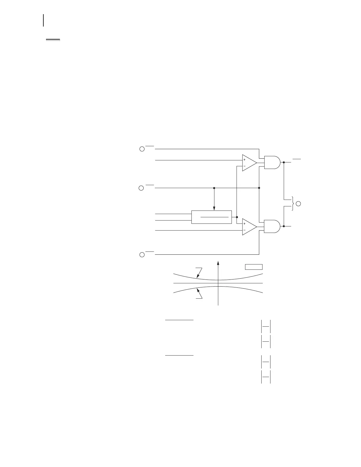
q To Figure 4.38 and Figure 4.39; w from Figure 4.23.
Figure 4.37 Negative-Sequence Voltage-Polarized Directional Element for
Negative-Sequence and Phase Overcurrent Elements
I
2
V
2
If Z2F Setting > 0, Forward Threshold = 1.25 • Z2F — 0.25 •
I
2
V
2
If Z2F Setting ≤ 0, Forward Threshold = 0.75 • Z2F — 0.25 •
Forward Threshold:
I
2
V
2
If Z2R Setting < 0, Reverse Threshold = 1.25 • Z2R + 0.25 •
I
2
V
2
If Z2R Setting ≥ 0, Reverse Threshold = 0.75 • Z2R + 0.25 •
Reverse Threshold:
Direction Element Characteristics
R2
X2
Forward Threshold
Reverse Threshold
Z2 PLANE
RDIRQ
(Reverse)
FDIRQ
(Forward)
50QF
Enable
Forward
Threshold
Reverse
Threshold
50QR
Re[V
2
•(I
2
•1∠Z1ANG)*]
|I
2
|
2
Z2 =
I
2
V
2
Relay
Word
Bits
Relay
Word
Bit
DIRQE
Relay
Word
Bits
Relay
Word
Bit
2
2
2
1