I.15
Date Code 20170927 Instruction Manual SEL-751 Relay
Synchrophasors
C37.118 Synchrophasor Protocol
Settings Affect
Message Contents
The SEL-751 allows several options for transmitting synchrophasor data.
These are controlled by Global settings described in Settings for
Synchrophasors on page I.4. You can select how often to transmit the
synchrophasor messages (MRATE) and which synchrophasors to transmit
(PHDATAV and PHDATAI). The SEL-751 automatically includes the
frequency and rate-of-change-of-frequency in the synchrophasor messages.
The relay can include as many as four user-programmable analog values in the
synchrophasor message, as controlled by Global setting NUMANA, and 0 or
16 digital status values, as controlled by Global setting NUMDSW.
The SEL-751 always includes the results of four synchrophasor trigger reason
SEL
OGIC control equations TREA1, TREA2, TREA3, and TREA4, and the
trigger SEL
OGIC control equation result PMTRIG, in the synchrophasor
message.
Communications
Bandwidth
A phasor measurement unit (PMU) that is configured to transmit a single
synchrophasor (positive-sequence voltage, for example) at a message rate of
once per second places little burden on the communications channel. As more
synchrophasors, analog values, or digital status words are added, or if the
message rate is increased, some communications channel restrictions come
into play.
The C37.118 synchrophasor message format always includes 18 bytes for the
message header and terminal ID, time information, status bits, and CRC value.
The selection of synchrophasor data, numeric format, programmable analog,
and programmable digital data adds to the byte requirements. You can use
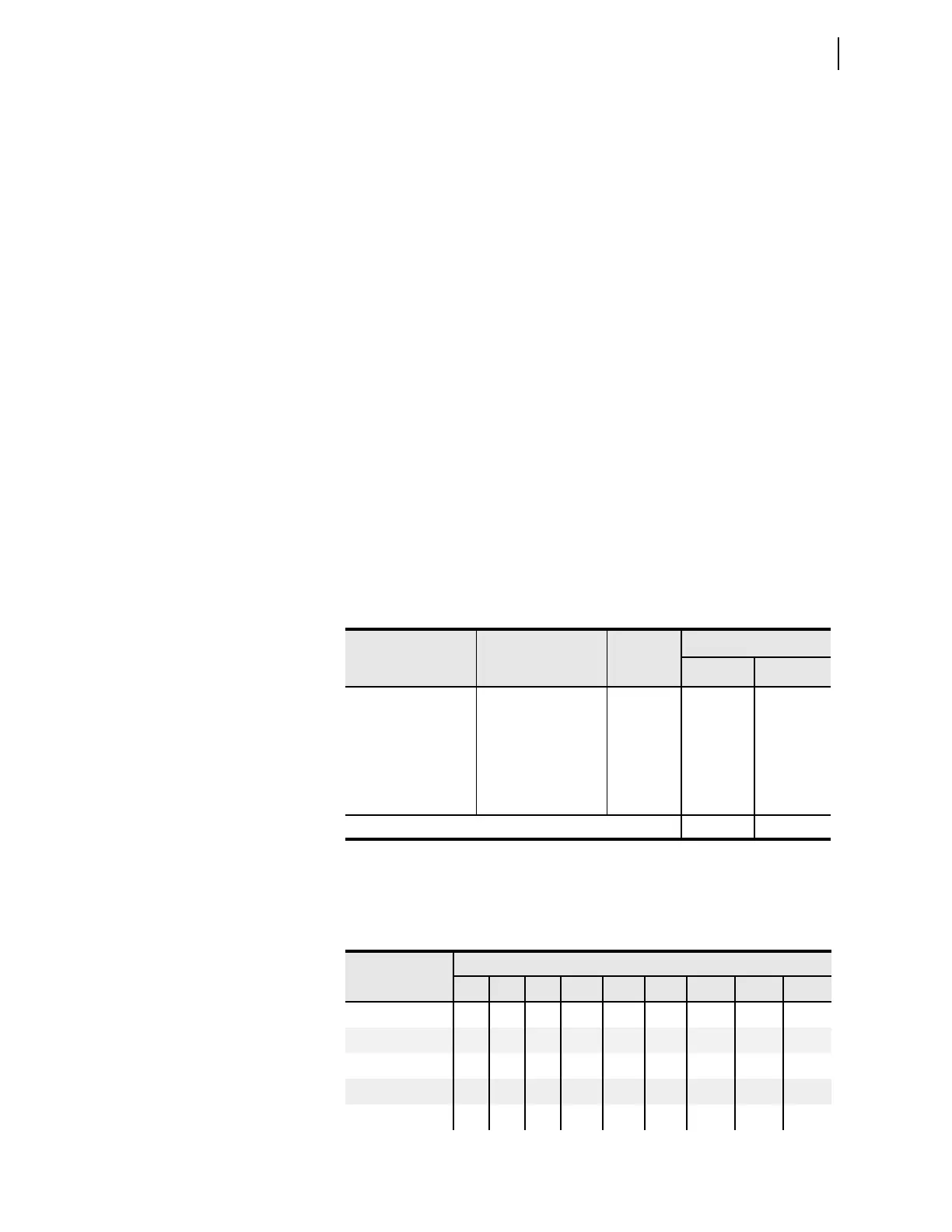
Table I.10 to calculate the number of bytes in a synchrophasor message.
Table I.11 lists the baud settings available on any SEL-751 serial port (setting
SPEED), and the maximum message size that can fit within the port
bandwidth. Blank entries indicate bandwidths of less than 20 bytes.
Table I.10 Size of a C37.118 Synchrophasor Message
Item
Possible Number
of Quantities
Bytes
per
Quantity
Number of Bytes
Minimum Maximum
Fixed 18 18
Synchrophasors 0–18 4 0 72
Frequency/DFDT 2 (fixed) 2 4 4
Analog Values 0–4 4 0 16
Digital Status Words 0–1 2 0 2
Total (Minimum and Maximum) 22 112
Table I.11 Serial Port Bandwidth for Synchrophasors (in Bytes) (Sheet 1 of 2)
Global Setting
MRATE
Port Setting SPEED
300 600 1200 2400 4800 9600 19200 38400 57600
1 21 42 85 170 340 680 1360 2720 4080
2 21 42 85 170 340 680 1360 2040
4 (60 Hz only) 21 42 85 170 340 680 1020
5 34 68 136 272 544 816
10 34 68 136 272 408