2.36
SEL-751 Relay Instruction Manual Date Code 20170927
Installation
AC/DC Control Connection Diagrams
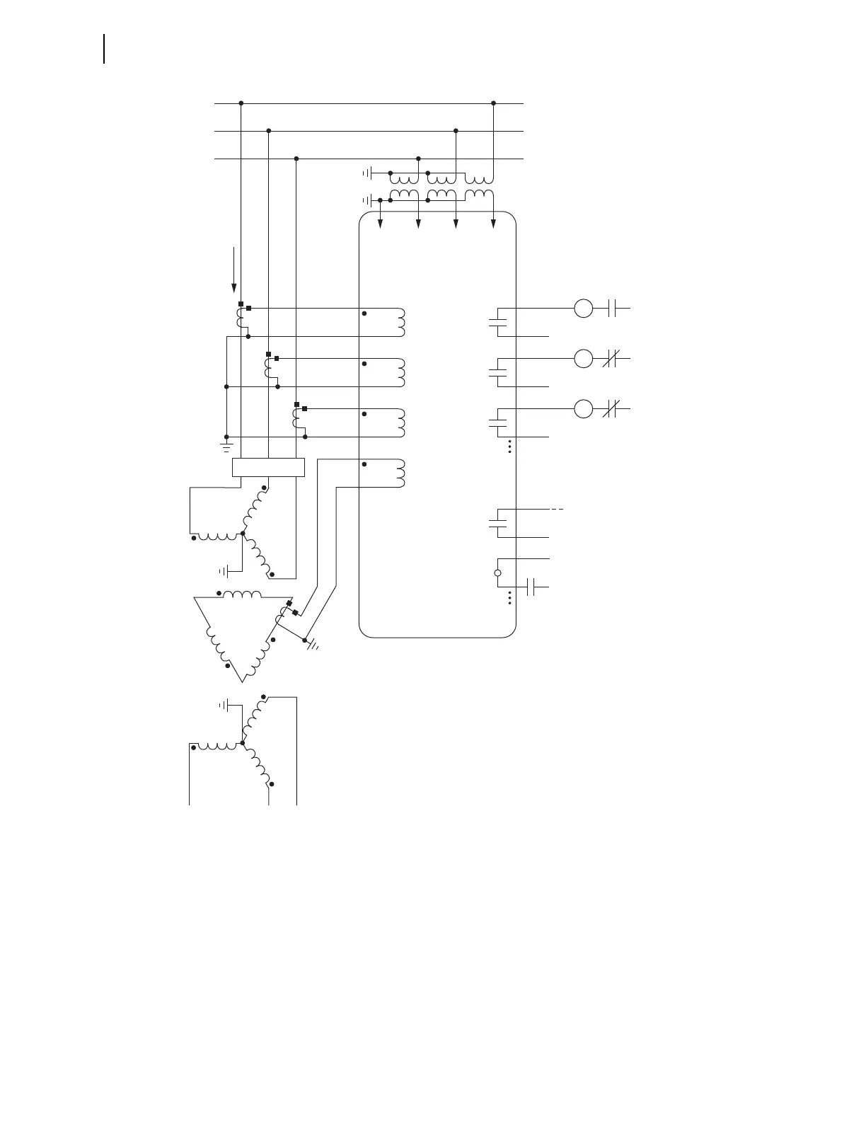
Voltages are necessary for voltage elements, synchronism-check elements, voltage-polarized directional elements, fault
location, and metering (e.g., voltage, KW, KVAR). INxxx and OUTxxx indicate user-configurable optional digital inputs and
outputs.
Although automatic reclosing is probably not necessary in this example, output contact OUT102 can close the circuit
breaker via initiation from various means (serial port communications, optoisolated input assertion, etc.), with desired
supervision (e.g., hot bus check).
Figure 2.27 SEL-751 Provides Overcurrent Protection for a Transformer Bank With a Tertiary
Winding (Wye-Connected PTs)
TC
Trip
Coil
52A
(+)
(—)
Trip
Circuit
IA
C
B
A
SEL-751 RELAY
OUT103
CC
Close
Coil
52B
(+)
(—)
Close
Circuit
IB OUT102
86
Lock
Out
86B
(+)
(—)
Breaker
Failure
Trip
Circuit
IC OUTxxx
IN
(+)
52A
to Annunciator, RTU,
SEL-2032/2030/2020,
or SEL-3530 RTAC
ALARM
OUT101
(+)
(—)
Breaker Status
INxxx
n
a
(Low-Side)
(Tertiary)
cb
N
52
VCNVBVA
Forward
Tripping
Direction