5.3
Date Code 20170927 Instruction Manual SEL-751 Relay
Metering and Monitoring
Metering
Fundamental
Metering
Table 5.1 details each of the fundamental meter data types in the SEL-751.
Section 8: Front-Panel Operations and Section 7: Communications describe
how to access the various types of meter data by using the relay front panel
and communications ports.
NOTE: Calculated phase-to-phase
voltages for wye-connected PTs are
available in the analog quantities and
can be selected as display points. See
Appendix L: Analog Quantities.
All angles are displayed between –180 and +180 degrees. The angles are
referenced to VAB or VAN (for delta- or wye-connected PT, respectively) or
IA. The angles are referenced to IA current if the secondary voltage
VAB < 13 V (for delta-connected PT) or the secondary voltage VAN < 13 V
(for wye-connected PT) when using the 300 Vac voltage inputs; or, VAN <
0.34 V (for wye-connected PT) when using the 8 Vac rms LEA voltage inputs.
Figure 5.2 shows an example of the METER command report.
The SEL-751 calculates percent unbalance current in one of two ways,
depending on the magnitude of the average current. When the average current
(I
av
) is greater than the CT rated current (I
NOM
) the relay calculates the
percent unbalance as shown in Equation 5.1.
Equation 5.1
When the average current is less than the I
NOM
current, the relay calculates
the percent unbalance as shown Equation 5.2.
Equation 5.2
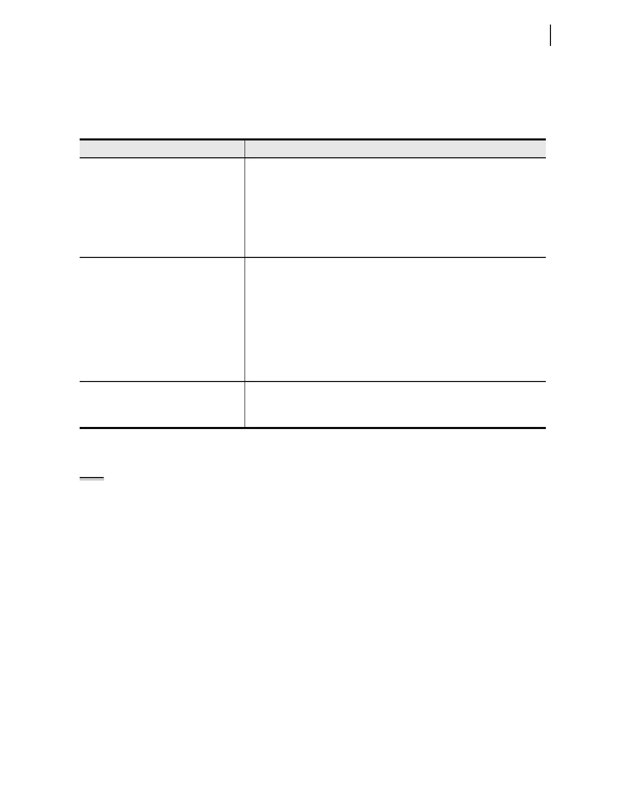
Table 5.1 Measured Fundamental Meter Values
Relay Option Meter Values
All Models Line Currents IA, IB, IC and IN (Core-Balance Ground Fault Current) magnitudes
(A primary) and phase angles (deg)
IG (Residual Ground Fault Current) magnitude (A primary) and phase angle (deg)
IAV (Average Current Magnitude A primary)
Positive-Sequence Current (I1 A primary)
Negative-Sequence Current (3I2 A primary)
Current Unbalance (%)
a
System Frequency (Hz) (FREQ)
With AC Voltage Inputs in Slot Z VAB, VBC, VCA or VAN, VBN, VCN, VG magnitudes (V primary) and phase
angles (deg)
VAV, Average Voltage (L-L or L-N [V primary])
Positive-Sequence Voltage (V1[V primary])
Negative-Sequence Voltage (3V2 [V primary])
Voltage Unbalance %
a
Real Power (kW)
b
Reactive Power (kVAR)
b
Apparent Power (kVA)
b
Power Factor
b
With Sync-Check and DC Station Battery
Voltages and Arc-Flash Detection Inputs
Option (2 AVI/4 AFDI Card
MOT...x70/L0x...)
VS (synchronism-check voltage) magnitude (V primary) and phase angle (deg)
Synchronism-check voltage frequency FREQS (Hz)
VDC (station battery voltage) (Vdc)
a
Current Unbalance % = 0 when IAV 0.25 * I
NOM
; Voltage Unbalance = 0 when VAV 0.25 * Vnm, where Vnm = VNOM/1.732 when wye;
VNOM when delta.
b
Three-phase measurements for delta-connected PTs and three-phase and single-phase measurements for wye-connected PTs.
UBI% 100
I
m
I
NOM
--------------
=