7.10
SEL-751 Relay Instruction Manual Date Code 20170927
Communications
Communications Interfaces
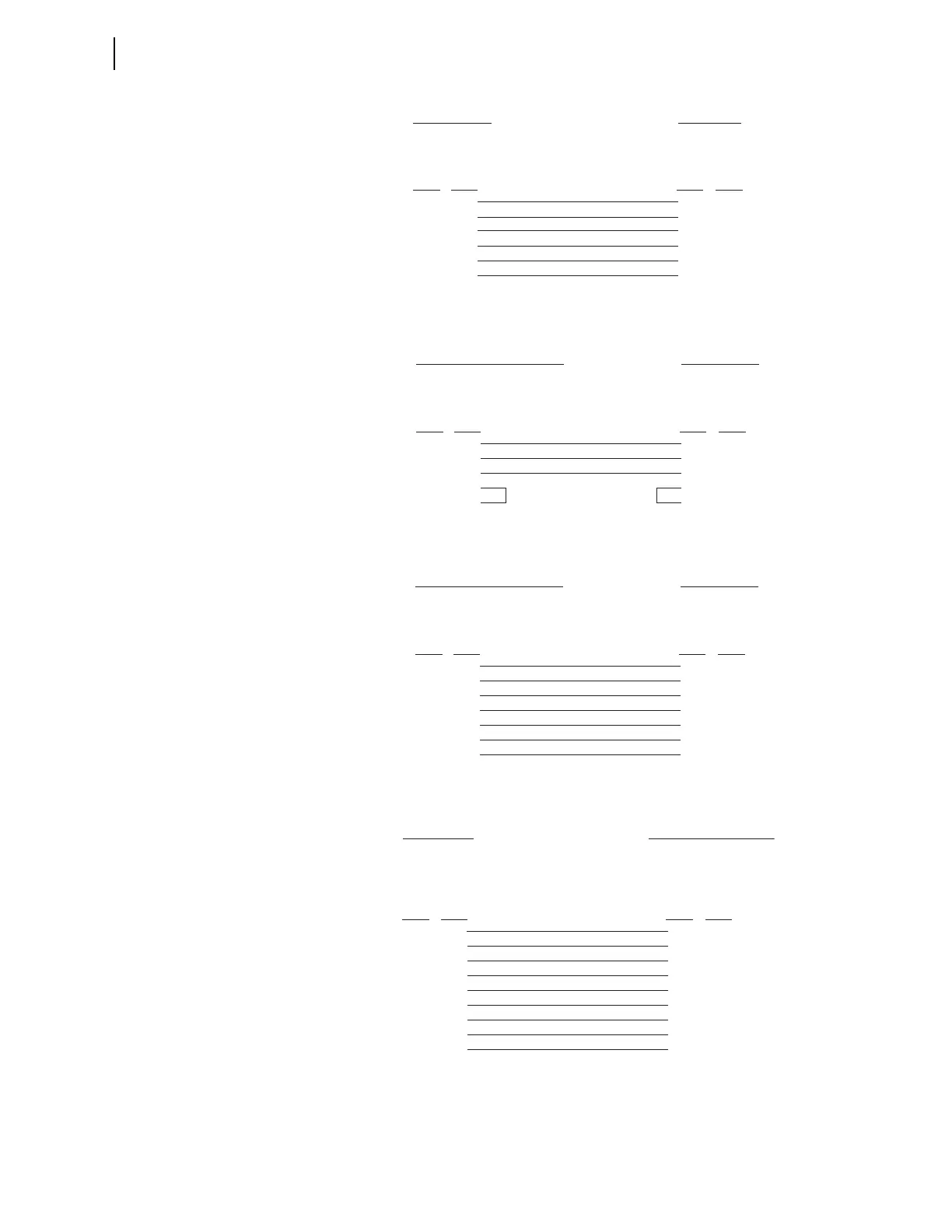
Figure 7.12 SEL Cable C222—SEL-751 to Modem
Figure 7.13 SEL Cable C272A—SEL-751 to SEL Communications
Processor Without IRIG-B Signal
Figure 7.14 SEL Cable C273A—SEL-751 to SEL Communications
Processor With IRIG-B Signal
Figure 7.15 SEL Cable C387—SEL-751 to SEL-3010
SEL-751 Relay
9-Pin Male
D Subconnector
25-Pin Female
D Subconnector
5
3
7
2
8
9
7
2
20
3
8
1
GND
TXD
RTS
RXD
CTS
GND
GND
TXD (IN)
DTR (IN)
RXD (OUT)
CD (OUT)
GND
Pin
Func.
Pin
Func.
Pin # Pin #
**DCE Device
**DCE = Data Communications E
ui
ment (Modem, etc.)
SEL Communications Processor
9-Pin Male
D Subconnector
9-Pin Male
D Subconnector
2
3
5
7
8
3
2
5
8
7
RXD
TXD
GND
RTS
CTS
TXD
RXD
GND
CTS
RTS
Pin
Func.
Pin
Func.
Pin # Pin #
SEL-751 Relay
SEL Communications Processor
9-Pin Male
D Subconnector
9-Pin Male
D Subconnector
2
3
4
5
6
7
8
3
2
4
5
6
8
7
RXD
TXD
IRIG+
GND
IRIG-
RTS
CTS
TXD
RXD
IRIG+
GND
IRIG-
CTS
RTS
Pin
Func.
Pin
Func.
Pin # Pin #
SEL-751 Relay
SEL-751 Relay
DTE*
9-Pin Male
D Subconnector
DCE**
9-Pin Male
D Subconnector
1
2
3
4
5
6
7
8
9
1
2
3
4
5
6
7
8
9
DCD***
RXD
TXD
GND
RTS
CTS
GND
+5 Vdc (IN)
RXD (OUT)
TXD (IN)
Not Used
GND
Not Used
RTS (IN)
CTS (OUT)
GND
Pin
Func.
Pin
Func.
Pin # Pin #
SEL-3010 Event Messenger
*DTE = Data Terminal Equipment
**DCE = Data Communications Equipment (Modem, etc.)
***DC Voltage (+5 V) not available on front-panel EIA-232 port