2.9
Date Code 20170927 Instruction Manual SEL-751 Relay
Installation
I/O Configuration
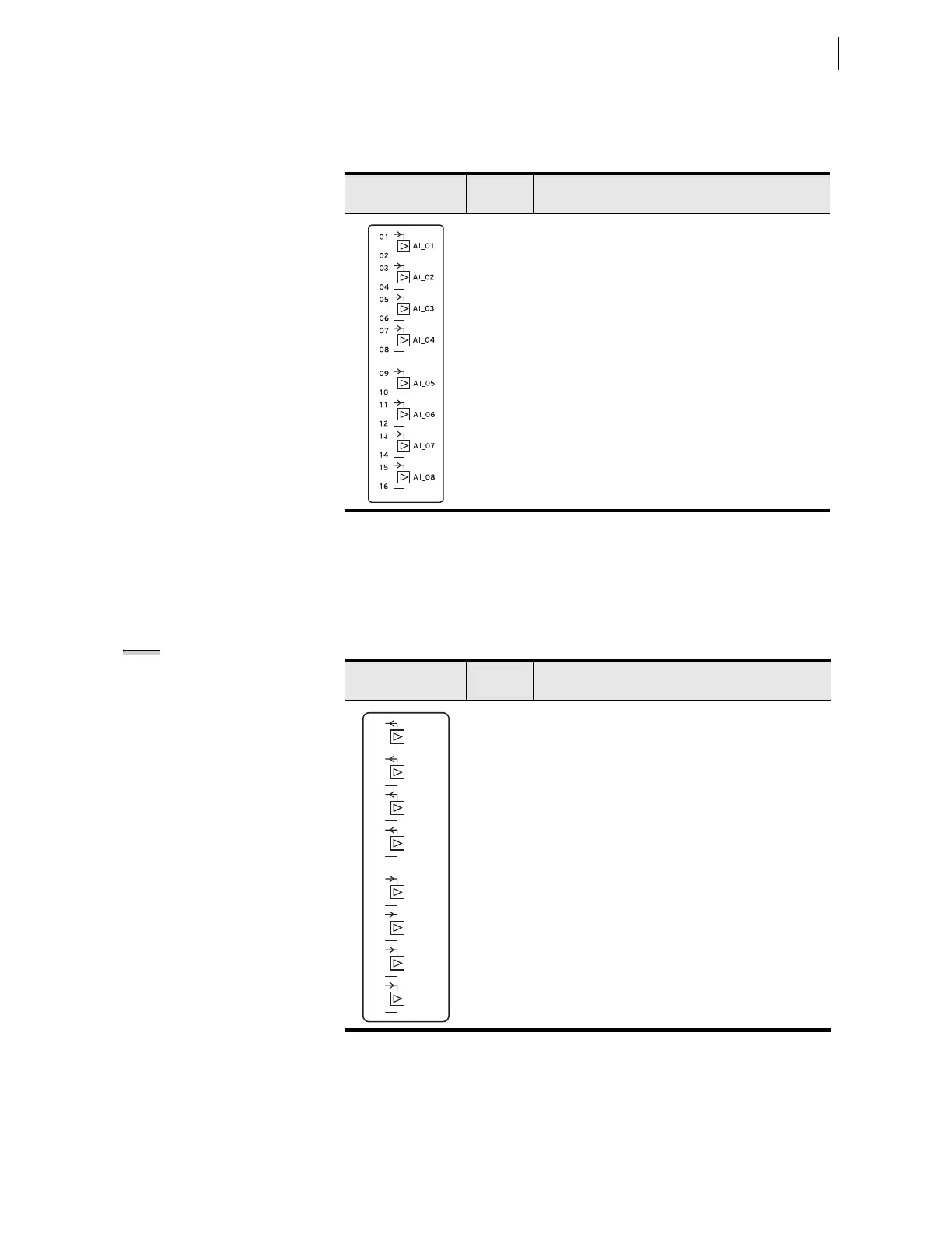
Analog Inputs Card
(8 AI)
Supported in any nonbase unit slot (Slot C through Slot E), this card has eight
analog inputs. Table 2.8 shows the terminal designation.
Analog
Inputs/Outputs Card
(4 AI/4 AO)
Supported in any one of the nonbase unit slots (Slot C through Slot E), this card
has four analog inputs and four analog outputs (AO). Table 2 .9 shows the
terminal designation.
Table 2.8 Eight Analog Inputs (8 AI) Card Terminal Designations
Side-Panel
Connections Label
Term i n al
Number
Description
a
a
x = 3, 4, or 5 (e.g., AI401, AI402, etc., if the card is installed in Slot D).
01, 02 AIx01, Transducer Input x01
03, 04 AIx02, Transducer Input x02
05, 06 AIx03, Transducer Input x03
07, 08 AIx04, Transducer Input x04
09, 10 AIx05, Transducer Input x05
11, 12 AIx06, Transducer Input x06
13, 14 AIx07, Transducer Input x07
15, 16 AIx08, Transducer Input x08
Table 2.9 Four Analog Inputs/Four Analog Outputs (4 AI/4 AO) Card
Terminal Designations
Side-Panel
Connections Label
Ter m inal
Number
Description
a
a
x=3, 4, or 5 (e.g., AI401, AI402, etc., if the card is installed in Slot D).
01, 02 AOx01, Analog Output x01
03, 04 AOx02, Analog Output x02
05, 06 AOx03, Analog Output x03
07, 08 AOx04, Analog Output x04
09, 10 AIx01, Transducer Input x01
11, 12 AIx02, Transducer Input x02
13, 14 AIx03, Transducer Input x03
15, 16 AIx04, Transducer Input x04
NOTE: Analog inputs cannot
provide loop power. Each analog
output is self powered and has an
isolated power supply.
AO_02
AO_0 1
AO_03
AO_04
AI_02
AI_0 1
AI_03
AI_04
08
05
06
02
04
09
03
10
11
12
13
14
15
16
07
01