2.4
SEL-751 Relay Instruction Manual Date Code 20170927
Installation
I/O Configuration
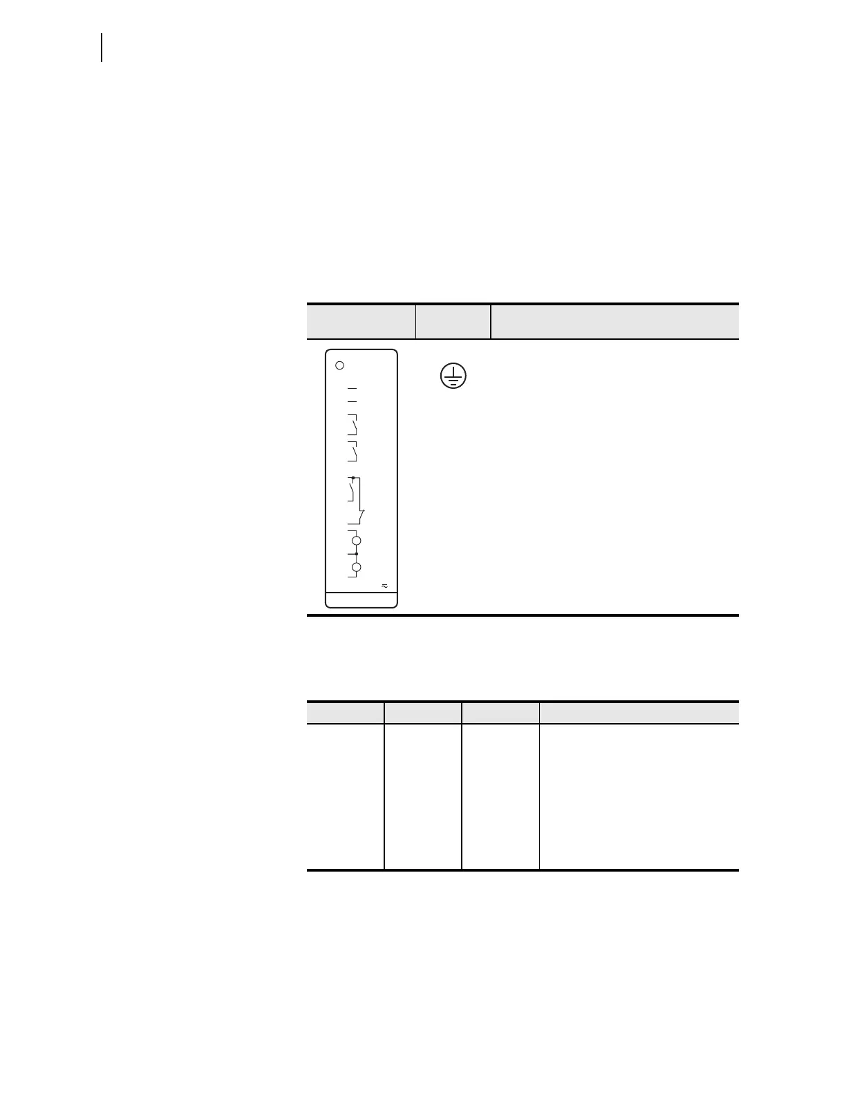
Power Supply Card
PSIO/2 DI/3 DO
(Slot A)
Select appropriate power supply option for the application:
➤ High Voltage: 110–250 Vdc, 110–240 Vac, 50/60 Hz
➤ Low Voltage: 24–48 Vdc
Select the appropriate digital input voltage option: 125 Vdc/Vac, 24 Vdc/Vac,
48 Vdc/Vac, 110 Vdc/Vac, 220 Vdc/Vac, or 250 Vdc/Vac.
This card is supported in Slot A of the SEL-751. It has two digital inputs and
three digital outputs (two normally open Form A contact outputs and one
Form C output). Table 2.1 shows the terminal designation for the
PSIO/2 DI/3 DO card.
Communications
Ports (Slot B)
Select the communications ports necessary for your application from the fol-
lowing base-unit options shown in Table 2.2.
PORT F supports the following protocols:
➤ SELBOOT
➤ Modbus RTU Slave
➤ SEL ASCII and Compressed ASCII
➤ SEL Settings File Transfer
Table 2.1 Power Supply Inputs (PSIO/2 DI/3 DO) Card Terminal Designations
Side-Panel
Connections Label
Te r m i na l
Number
Description
Ground connection
A01, A02 Power supply input terminals
A03, A04 OUT101, driven by OUT101 SEL
OGIC
control equation
A05, A06 OUT102, driven by OUT102 SEL
OGIC
control equation
A07, A08, A09 OUT103, driven by OUT103 SEL
OGIC
control equation
A10, A11 IN101, drives IN101 element
A12, A11 IN102, drives IN102 element
A100
OUT_0 1
OUT_02
IN_01
IN_02
10
11
08
12
INPUTS:
05
06
04
03
02
01
GND
+/H
—/N
POWER
OUT_03
09
07
Table 2.2 Communications Ports
Port Location Feature Description
F Front Panel Standard Nonisolated EIA-232 serial port
1 Rear Panel Optional (Single/Dual) Isolated 10/100BASE-T
Ethernet copper port or 100BASE-FX
Ethernet fiber-optic port
2 Rear Panel Optional Isolated multimode fiber-optic serial
port with ST connectors
3 Rear Panel Standard Either nonisolated EIA-232 or isolated
EIA-485 serial port