4.78
SEL-751 Relay Instruction Manual Date Code 20170927
Protection and Logic Functions
Group Settings (SET Command)
Load-Encroachment Settings
The SEL-751 phase directional elements are supervised by a load- encroach-
ment function that prevents element misoperation under heavy load. You must
set load impedance magnitude and angles to the necessary values to enable
load-encroachment supervision. The relay uses these settings to define a
region in the impedance plane where operation of the three-phase elements is
prevented. This allows you to make the phase protection element reach the set-
tings without concern for misoperation under heavy load.
Note that a positive-sequence impedance calculation (Z
1
) is made in the load-
encroachment logic in Figure 4.54. Load is largely a balanced condition, so
apparent positive-sequence impedance is a good load measure. The load-
encroachment logic operates only if the positive-sequence current (I
1
) is
greater than the positive-sequence threshold defined in Figure 4.54. For a bal-
anced load condition, I
1
= phase current magnitude.
Forward load (load flowing out) lies within the hatched region labeled
ZLOUT. Relay Word bit ZLOUT asserts to logical 1 when the load lies within
this hatched region.
Reverse load (load flowing in) lies within the hatched region labeled ZLIN.
Relay Word bit ZLIN asserts to logical 1 when the load lies within this
hatched region.
Relay Word bit ZLOAD is the OR-combination of ZLOUT and ZLIN:
ZLOAD := ZLOUT OR ZLIN
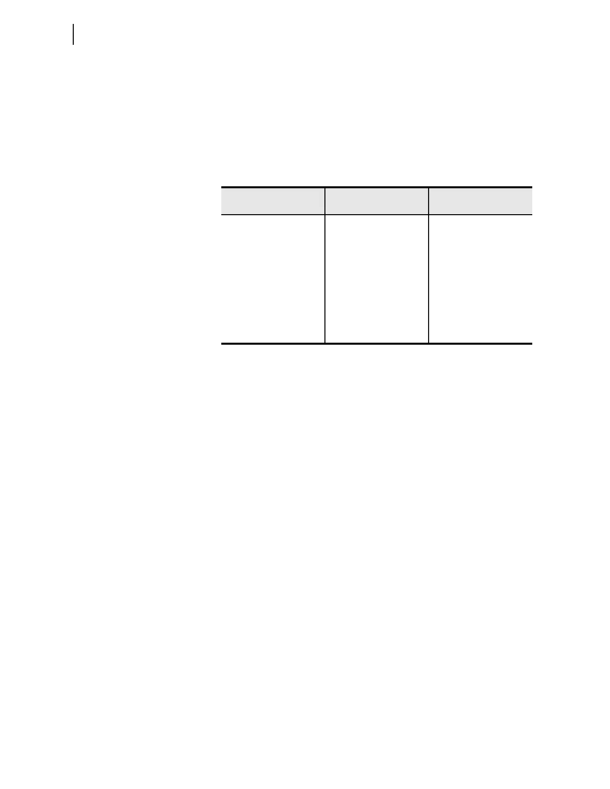
Table 4.27 Load-Encroachment Settings
Setting Prompt Setting Range
Setting Name :=
Factory De fault
LOAD ENCROACH EN Y, N ELOAD := N
FWD LD IMPEDANCE 0.10–128.00 ohm
a
a
Setting ranges and default ohm values shown are for 5 A nominal CT rating. Multiply by 5 for
1A CTs.
ZLF := 6.50
a
POS-FWD LD ANGLE –90.00 to 90.00 deg PLAF := 30.00
NEG-FWD LD ANGLE –90.00 to 90.00 deg NLAF := –30.00
REV LD IMPEDANCE 0.10–128.00 ohm
a
ZLR := 6.50
a
POS-REV LD ANGLE 90.00 to 270.00 deg PLAR := 150
NEG-REV LD ANGLE 90.00 to 270.00 deg NLAR := 210.00