2.48
SEL-751 Relay Instruction Manual Date Code 20170927
Installation
Arc-Flash Protection: System Installation
tional splice connectors, refer to the SEL-C814 Arc-Flash Detection (AFD)
Fiber Cables and Accessories MOT. The losses and budget values shown in
Table 2.19 are typical values.
Link Optical Loss Calculation Examples
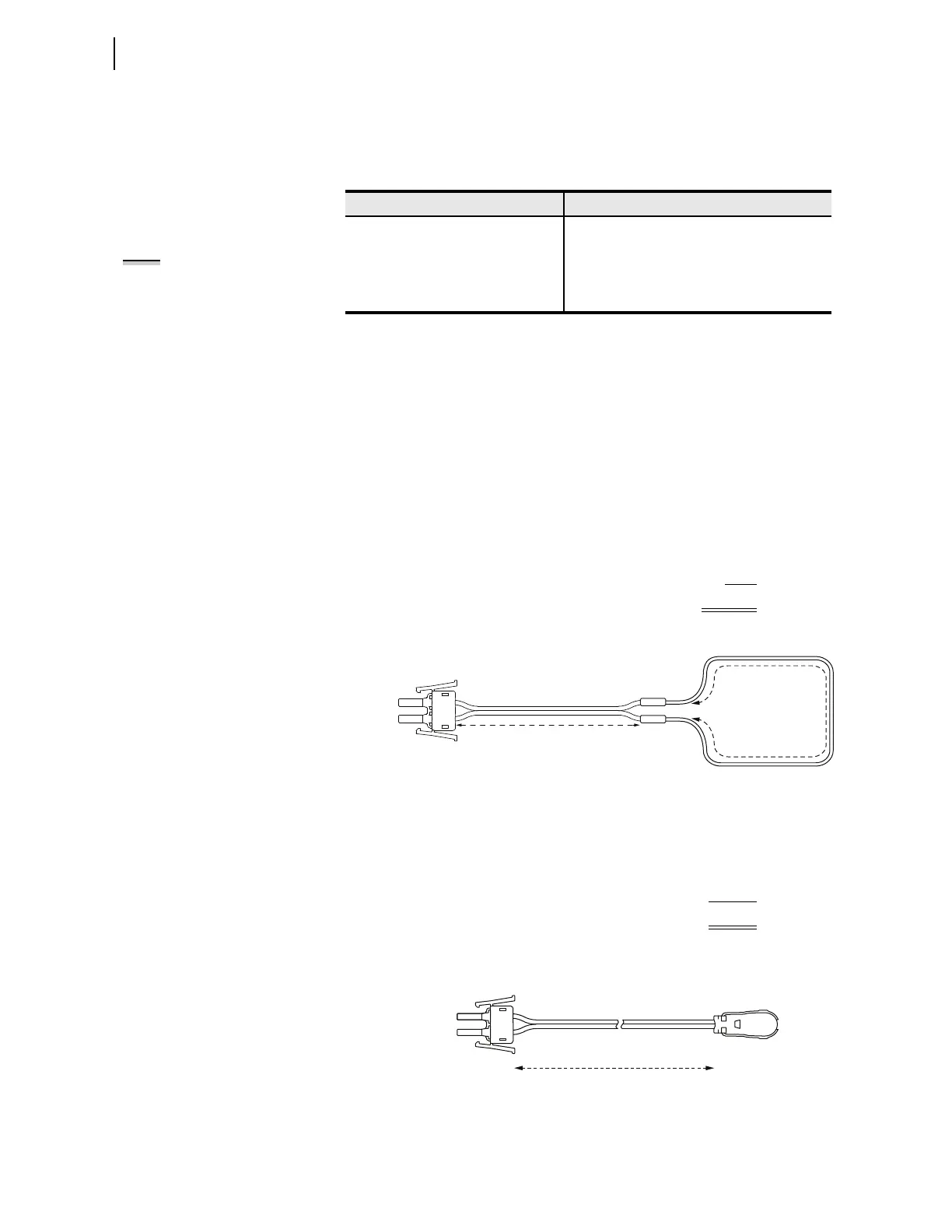
This example shows a bare-fiber sensor with two V-Pin or ST connectors and
an A dimension of 15 meters and a B dimension of 40 meters. Two connectors
is the standard configuration, as shown in Figure 2.45.
Figure 2.45 Bare-Fiber Sensor Assembly With Two Splices
This example shows a point sensor with an A dimension of 30 m, as shown in
Figure 2.46.
Figure 2.46 Point Sensor Assembly
Table 2.19 Optical Budget Calculations
Link Budget
a
a
Link budget is calculated after allowing for the losses of the dual V-pin latch. When using a
point sensor it allows for the sensor loss as well.
Loss Data
b
b
Link losses are calculated by adding up the fiber loss and the splice connector losses. The link
losses should be less than the link budget.
Bare-Fiber Sensor 17 dB ST connector splice 2 dB
Point Sensor 12.25 dB V-Pin connector splice 2 dB
Bare-fiber 0.175 dB/m
Jacketed fiber 0.175 dB/m
NOTE: Jacketed fiber in a zipcord
duplex configuration includes two
fiber lengths. Loss calculations must
account for the total length of the
fiber. This is accounted for in the
examples as a “x 2” multiplier.
Link Budget 17 dB
– (2 dB x # of connector splices) –4 dB
– (0.175 dB/m x A dimension x 2) –5.25 dB
– (0.175 dB/m x B dimension) –7 dB
Total Link Losses = –16.25 dB
Link Budget 12.25 dB
– (0.175 dB/m x A dimension x 2) –10.5 dB
Total Link Losses = –10.5 dB
V-Pin
Terminators
B Meters
Clear-Jacketed Fiber
Dual V-Pin
Latch
V-Pin or
ST Splice
Connector
A Meters
Black-Jacketed Fiber Zipcord Duplex
Black-Jacketed Fiber Zipcord Duplex
V-Pin
Terminators
Dual V-Pin
Latch
Sensors
1–35 Meters