4.40
SEL-751 Relay Instruction Manual Date Code 20170927
Protection and Logic Functions
Group Settings (SET Command)
q From Table 4.20; w to Figure 4.32 and Figure 4.33; e from Figure 4.24.
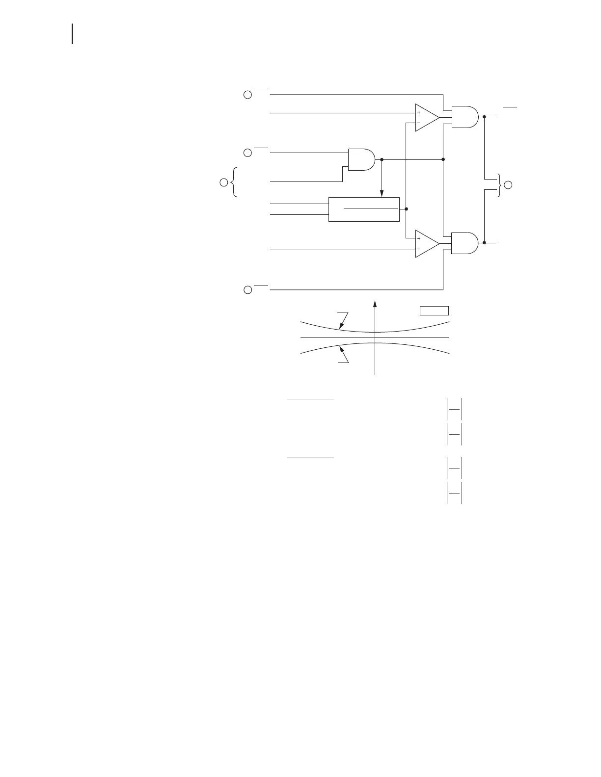
Figure 4.27 Zero-Sequence Voltage-Polarized Directional Element
The 3V0 input to Figure 4.27 may be either a calculated value (when
VSCONN := VS and DELTA_Y := WYE) or a measured value (when
VSCONN := 3V0). See Zero-Sequence Voltage Sources on page 4.33.
I
0
V
0
If Z0F Setting > 0, Forward Threshold = 1.25 • Z0F — 0.25 •
I
0
V
0
If Z0F Setting ≤ 0, Forward Threshold = 0.75 • Z0F — 0.25 •
Forward Threshold:
I
0
V
0
If Z0R Setting < 0, Reverse Threshold = 1.25 • Z0R + 0.25 •
I
0
V
0
If Z0R Setting ≥ 0, Reverse Threshold = 0.75 • Z0R + 0.25 •
Reverse Threshold:
Direction Element Characteristics
R0
X0
Forward Threshold
Reverse Threshold
Z0 PLANE
RDIRV
(Reverse)
FDIRV
(Forward)
Best Choice
Ground
Directional
Logic
50GF
Enable
Forward
Threshold
DIRVE
Reverse
Threshold
50GR
Re[3V
0
•(I
G
•1∠Z0MTA)*]
|I
G
|
2
Z0 =
I
G
3V
0
Relay
Word
Bits
Relay
Word
Bit
Relay
Word
Bit
Relay
Word
Bit
choice that is asserted
(I
G
= 3I
0
)
(Residual)
DIRVE is highest
3
3
3
1
2