4.19
Date Code 20170927 Instruction Manual SEL-751 Relay
Protection and Logic Functions
Group Settings (SET Command)
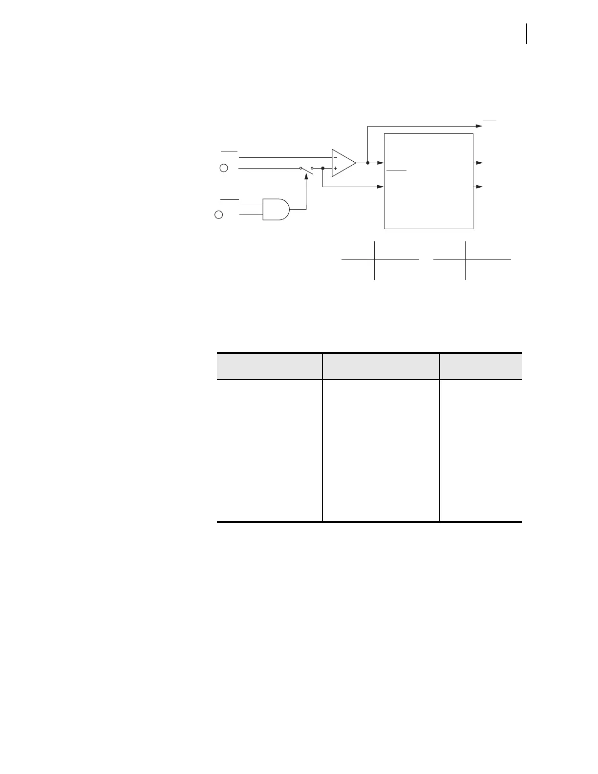
The maximum phase time-overcurrent elements, 51P1T and 51P2T, respond
to the highest of A-, B-, and C-phase currents as shown in Figure 4.6.
n = 1 or 2.
q From Figure 4.2; w To Figure 4.41.
Figure 4.6 Maximum Phase Time-Overcurrent Elements 51P1T and 51P2T
Table 4.14 Negative-Sequence Time-Overcurrent Settings
Setting Prompt Setting Range
Setting Name :=
Fac to ry Defa ult
TOC TRIP LVL OFF, 0.25–24.00 A
a
,
0.05–4.80 A
b
a
For I
NOM
= 5 A.
b
For I
NOM
= 1 A.
51QP := 6.00
51QP := 1.2
TOC CURVE SEL U1, U2, U3, U4, U5, C1, C2,
C3, C4, C5
51QC := U3
TOC TIME DIAL 0.50–15.00
c
,
0.01–1.50
d
c
For 51_C := U_.
d
For 51_C := C_.
51QTD := 3.00
EM RESET DELAY Y, N 51QRS := N
CONST TIME ADDER 0.00–1.00 sec 51QCT := 0.00
MIN RESPONSE TIM 0.00–1.00 51QMR := 0.00
TOC TRQ CONTROL SEL
OGIC 51QTC := 1
51PnP
Setting
51PnTC
Torque Control Switch
Torque
Control
51PnP (Pickup)
51PnR (Reset)
51PnT (Curve
Timeout)
Torque
Control Torque Control
State Switch Position
Logical 1 Closed
Logical 0 Open
Setting
51PnRS= Reset Timing
Y Electromechanical
N 1 Cycle
Relay
Word
Bits
SEL
OGIC
Setting
51PnT Phase
Time-Overcurrent Element
Curve Timing and Reset Timing
Settings
51PnP Pickup
51PnC Curve Type
51PnTD Time Dial
51PnRS Electromechanical
Reset? (Y/N)
51PnCT Const. Time Add.
51PnMR Min. Response
|IP|
1
P1DIR
2