2.19
Date Code 20170927 Instruction Manual SEL-751 Relay
Installation
Relay Connections
Relay Connections
Side-Panel and Rear-
Panel Diagrams
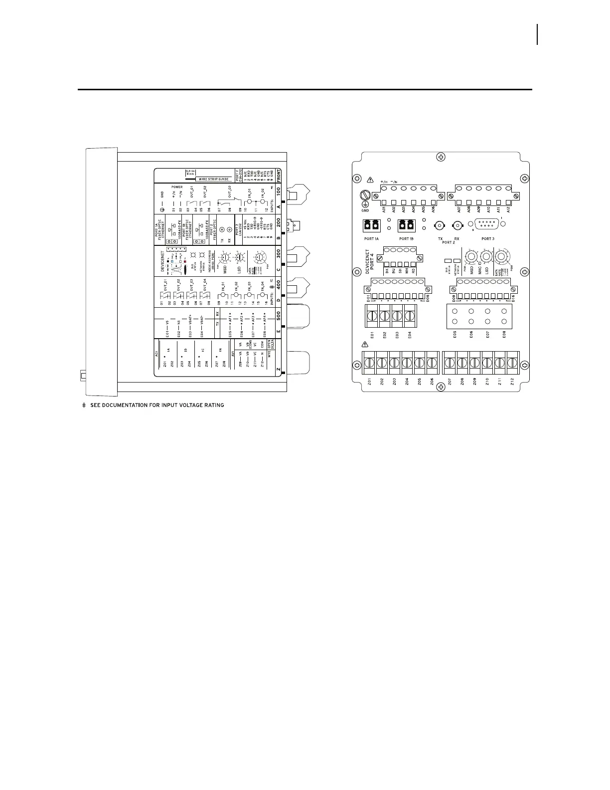
The physical layout of the connectors on the side-panel and rear-panel
diagrams of seven sample configurations of the SEL-751 are shown in
Figure 2.8 through Figure 2.14.
Figure 2.8 Dual Fiber Ethernet With 2 AVI/4 AFDI Voltage Option With Arc-Flash
DetectorInputs,DeviceNetCard,and Fast Hybrid 4 DI/4 DO Card (RelayMOT751501AA3CA70850830)
(A) Side-Panel Input and Output Designations (B) Rear-Panel Layout