8.16
SEL-751 Relay Instruction Manual Date Code 20170927
Front-Panel Operations
Two-Line Display Front Panel
pushbutton, and then pressing the pushbutton again asserts the corresponding
PBn_PUL Relay Word bit for another processing interval. The pushbutton
LEDs are independent of the pushbutton.
Pushbutton LEDs are programmable by using the front-panel settings
PBnm_LED (where n = 1 through 8 and m = A or B). PBnm _LED settings are
SEL
OGIC control equations that, when asserted, illuminate the corresponding
LED for as long as the input is asserted. When the input deasserts, the LED
also deasserts without latching. Use PBnmLEDC settings to select the LED
color (R–red, G–green, A–amber) for both the asserted and deasserted state of
the LED.
Using SEL
OGIC control equations, you can readily change the default LED
and pushbutton functions. Use the slide-in label to mark the pushbuttons and
pushbutton LEDs with custom names to reflect any programming changes that
you make. Included on the SEL-751 Product Literature CD are word
processor templates for printing slide-in labels. See the instructions included
in the Configurable Label kit for more information on changing the slide-in
labels.
Table 8.4 describes front-panel operator controls based on the factory-default
settings and operator control labels.
NOTE: The reduced SEL-751 model
with four pushbuttons does not
support AUX1 though AUX4
(i.e., PB05 through PB08).
Table 8.4 SEL-751 Front-Panel Operator Control Functions (Sheet 1 of 2)
Press the AUX operator control pushbutton to enable/disable user-programmed auxiliary con-
trol. You can program the corresponding LED to illuminate during the enabled state.
NOTE: The AUX operator control does not perform any function with the factory settings.
Also, AUX1 to AUX4 pushbuttons do not perform any function in the factory-default
settings. These pushbuttons are available to configure any application you may select.
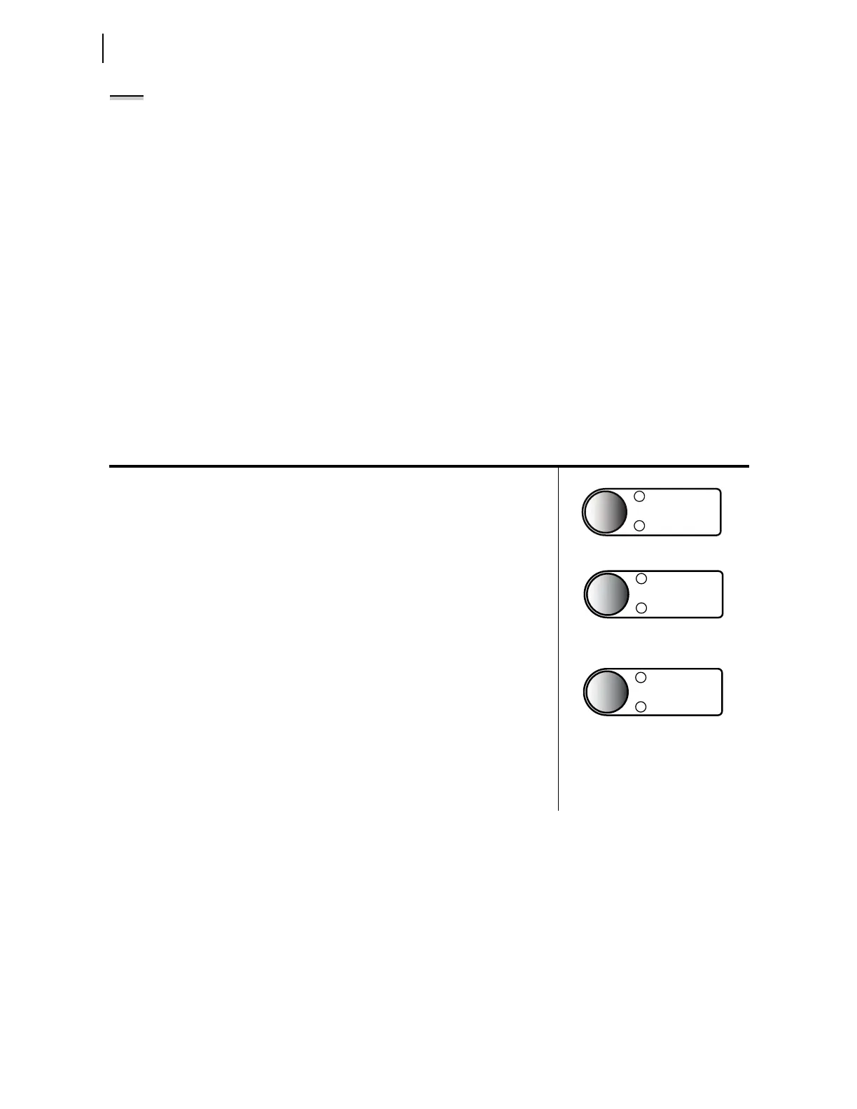
For Models With Reclosing Option:
The pushbutton is not used in the factory settings, but you can easily program it to perform a
user control function.
The top LED is programmed to indicate RECL RESET (Relay Word bit 79RS—reclosing
relay in RESET state) in the factory settings. The bottom LED is programmed to indicate
RECL LOCKOUT (Relay Word bit 79LO—reclosing relay in LOCKOUT state).
Continually press the LOCK operator control pushbutton for three (3) seconds to engage/dis-
engage the lock function (Latch LT02 functions as Lock with the latch in reset state equiva-
lent to the engaged lock). While this pushbutton is pressed, the corresponding LED flashes
on and off, indicating a pending engagement or disengagement of the lock function. The
LED illuminates constantly to indicate the engaged state. While the lock function is
engaged, the following operator control is “locked in position” (assuming factory-default
settings): CLOSE.
While “locked in position,” this operator control cannot change state if pressed—the corre-
sponding LEDs remain in the same state. When the lock function is engaged, the CLOSE
operator control cannot close the breaker, but the TRIP operator control can still trip the
breaker.