4.16
SEL-751 Relay Instruction Manual Date Code 20170927
Protection and Logic Functions
Group Settings (SET Command)
When the overcurrent trip delay (50P1D through 50P4D, 50N1D through
50N4D, 50G1D through 50G4D and 50Q1D through 50Q4D) is set to OFF,
the time delayed overcurrent element is disabled and the output Relay Word
bits (50P1T through 50P4T, 50N1T through 50N4T, 50G1T through 50G4T
and 50Q1T through 50Q4T) keep deasserted.
Pickup and Reset Time Curves
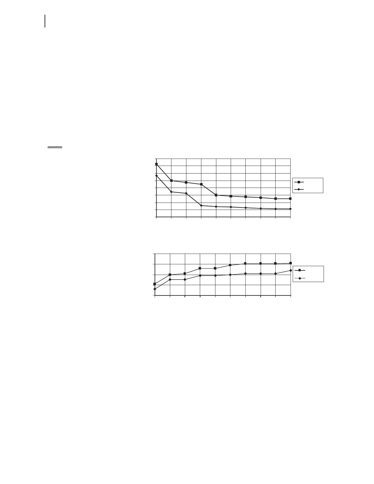
Figure 4.3 and Figure 4.4 show pickup and reset time curves applicable to all
nondirectional instantaneous overcurrent elements with sinusoidal waveforms
applied (60 Hz or 50 Hz relays). These times do not include output contact
operating time and, thus, are accurate for determining element operation time
for use in internal SEL
OGIC control equations. Output contact pickup/dropout
time is approximately 4 ms (0.25 cycle for a 60 Hz relay; 0.20 cycle for a
50 Hz relay).
NOTE: The pickup time curve in
Figure 4.3 is not valid for conditions
with a saturated CT, where the
resultant current to the relay is
nonsinusoidal.
Figure 4.3 Instantaneous Overcurrent Element Pickup Time Curve
Figure 4.4 Instantaneous Overcurrent Element Reset Time Curve
Time-Overcurrent Elements
One level of inverse-time element is available for A-, B-, C-phases, and nega-
tive-sequence overcurrent. Also, two levels of inverse-time elements are avail-
able for maximum phase, neutral, and residual overcurrent. See Table 4 .12
through Table 4.16 for available settings.
You can select from five U.S. and five IEC inverse characteristics. Table 4 .1 7
and Table 4.18 show equations for the curves and Figure 4.10 through
Figure 4.19 show the curves. The curves and equations shown do not account
for constant time adder and minimum response time (settings 51_CT and
51_MR respectively, each assumed equal to zero). Use the 51_CT if you want
to raise the curves by a constant time. Also, you can use the 51_MR if you
want to ensure the curve times no faster than a minimum response time.
0
0.2
0.4
0.6
0.8
1
1.2
1.4
1.6
1.2 2 3 4 5 6 7 8 9 10
Applied Current (Multiples of Pickup Setting)
Pickup Time (Cycles)
Maximum
Minimum
Applied Current (Multiples of Pickup Setting)
Reset Time (Cycles)
Maximum
Minimum
2
1.5
1
0.5
0
1.2 2 3 4 5 6 7 8 9 10