4.89
Date Code 20170927 Instruction Manual SEL-751 Relay
Protection and Logic Functions
Group Settings (SET Command)
RTD-Based Protection
RTD Input Function
When you connect an SEL-2600 RTD Module (select E49RTD := EXT) or
order the internal resistance temperature device (RTD) card option (select
E49RTD := INT), the SEL-751 offers several protection and monitoring func-
tions, settings for which are described in Table 4 . 31. See
Figure 2.15 for the
RTD module fiber-optic cable connections. If the relay does not have internal
or external RTD inputs, set E49RTD := NONE.
RTD Location
The relay allows you to independently define the location of each monitored
RTD by using the RTD location setting, RTDnLOC.
Define the RTD location settings by using the following suggestions:
➤ If an RTD is not connected to an input or has failed in place and is
not to be replaced, set the RTD location for that input equal to OFF.
➤ For RTDs embedded in motor stator windings, set the RTD
location equal to WDG.
➤ For inputs connected to RTDs measuring bearing race
temperature, set the RTD location equal to BRG.
➤ For the input connected to an RTD measuring ambient motor
cooling air temperature, set the RTD location equal to AMB.
Only one ambient temperature RTD is allowed.
➤ For inputs connected to monitor temperatures of another
apparatus, set the RTD location equal to OTH.
If an RTD location setting is equal to OFF, the relay does not request that an
RTD type setting be entered for that input.
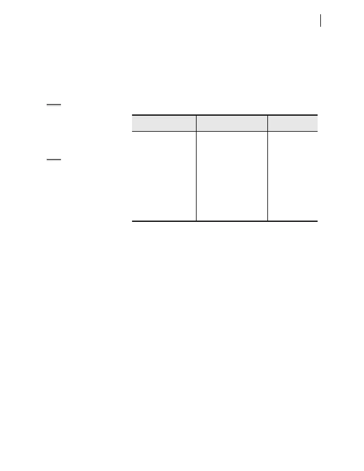
Table 4.31 RTD Settings
Setting Prompt Setting Range
Setting Name :=
Fac to ry Defa ult
RTD ENABLE INT, EXT, NONE E49RTD := NONE
RTD1 LOCATION OFF, WDG, BRG, AMB, OTH RTD1LOC := OFF
RTD1 TYPE PT100, NI100, NI120, CU10 RTD1TY := PT100
RTD1 TRIP LEVEL OFF, 1–250°C TRTMP1 := OFF
RTD1 WARN LEVEL OFF, 1–250°C ALTMP1 := OFF
•
•
•
•
•
•
•
•
•
WIND TRIP VOTING Y, N EWDGV := N
BEAR TRIP VOTING Y, N EBRGV := N
NOTE: The SEL-751 can monitor as
many as 10 RTDs connected to an
internal RTD card or as many as
12 RTDs connected to an external
SEL-2600 RTD Module. Table 4.31
shows Location, Type, and Trip/Warn
Level settings only for RTD1; settings
for RTD2–RTD12 are similar.
NOTE: RTD curves in SEL products
are based on the DIN/IEC 60751
standard.