4.121
Date Code 20170927 Instruction Manual SEL-751 Relay
Protection and Logic Functions
Group Settings (SET Command)
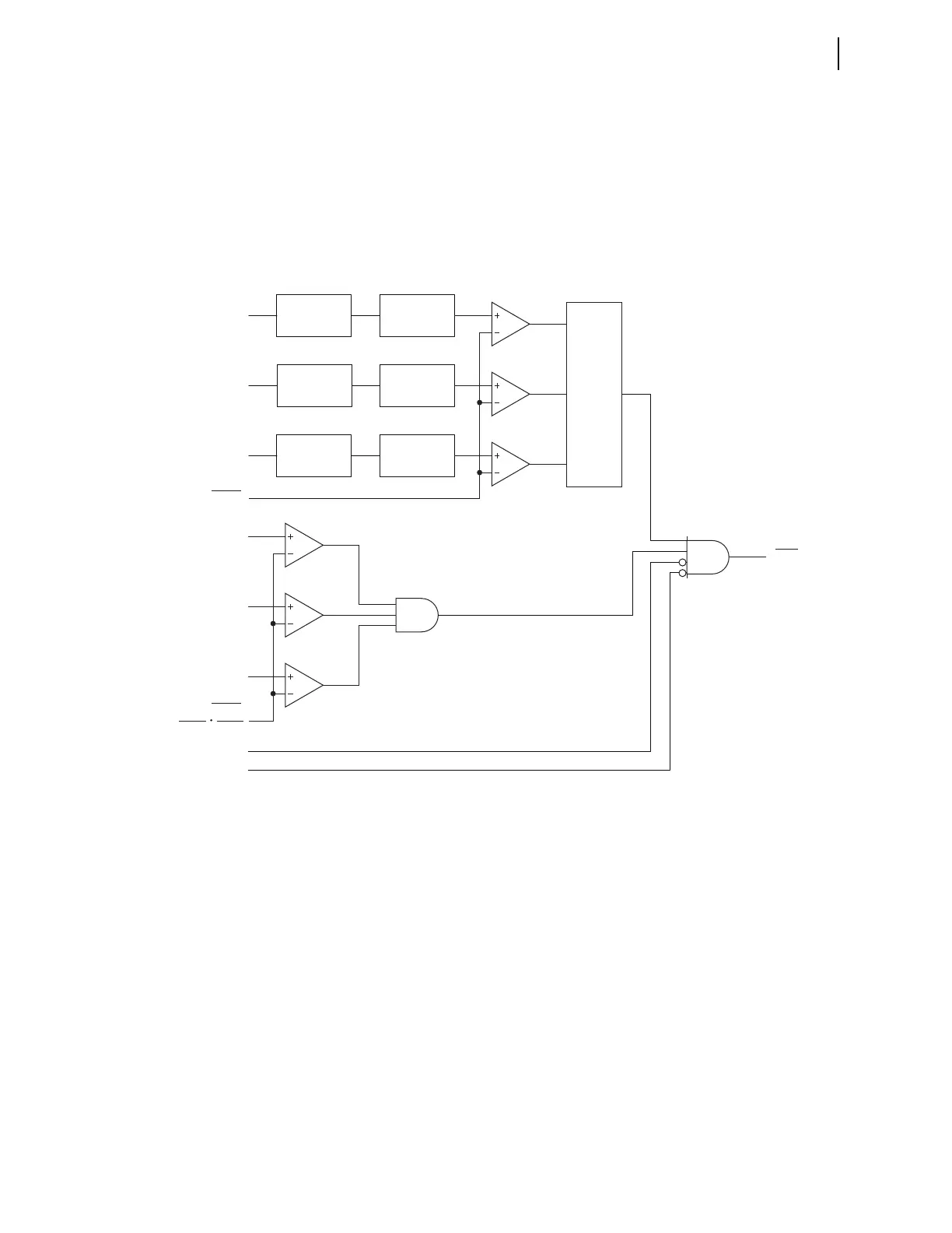
Vector Shift Element Logic
The logic diagram of the vector shift element in Figure 4.74 displays the steps
performed to detect an islanding condition:
➤ Zero-crossing based period estimation
➤ Angle shift calculation and angle shift threshold check
➤ Angle shift count calculator
➤ Blocking conditions
Figure 4.74 Logic Diagram of the Vector Shift Element
The element performs period calculations on each of the voltage inputs, VA,
VB, and VC. Zero-crossing detection logic is used to perform the period calcu-
lations. The time stamps of two consecutive positive-going zero-crossings or
two consecutive negative-going zero-crossings are used in determining the
period. The relay establishes a reference period for each phase using the previ-
ous 32 period measurements. The initialization period for this element
requires at least 16 cycles of voltage signal to establish an accurate reference
period. During the initialization period, this element does not detect an island-
ing condition.
In each quarter-cycle, the relay calculates the difference between the present
period on each phase with the corresponding reference period. This difference
is expressed in degrees to determine the angle shift and compared against the
setting 78VSAPU. If the calculated angle shift is greater than the angle shift
threshold setting 78VSAPU, the comparator output for the corresponding
phase will be one; this output is fed to the angle shift count calculator logic.
Zero-Crossing
Detector
Angle Shift
Calculation
Angle Shift
Calculation
Angle Shift
Calculation
Count
Calculator
OUTPUT = 1
if count > 4
|VC
1
|
VA
1
VB
1
VC
1
Zero-Crossing
Detector
Zero-Crossing
Detector
Settings
78VSAPU
Setting
|VA
1
|
|VB
1
|
78VSBL
78VSO
Relay
Word
Bit
1
The logic diagram shown applies when DELTA_Y := WYE.
When DELTA_Y := DELTA, the quantities VA, VB, and VC are replaced by VAB, VBC, and VCA, respectively. In addition, VNOM is not divided by √3.
The element is disabled when VNOM := OFF.
VNOM := OFF
78VS59
100
√3
VNOM
1