4.144
SEL-751 Relay Instruction Manual Date Code 20170927
Protection and Logic Functions
Group Settings (SET Command)
Reclosing Relay Shot Counter
Refer to Figure 4.85. The shot counter increments for each reclose operation.
For example, when the relay is timing on open interval 1, 79OI1, it is at shot =
0. When the open interval times out, the shot counter increments to shot = 1
and so forth for the set open intervals that follow. The shot counter cannot
increment beyond the last shot for automatic reclosing (see Determination of
Number of Reclosures (Last Shot) on page 4.142). The shot counter resets
back to shot = 0 when the reclosing relay returns to the Reset State.
When the shot counter is at a particular shot value (e.g., shot = 2), the corre-
sponding Relay Word bit asserts to logical 1 (e.g., SH2 = logical 1).
The shot counter also increments for sequence coordination operation. The
shot counter can increment beyond the last shot for sequence coordination
(see Sequence Coordination Setting (79SEQ) on page 4.150).
Reclose Initiate and Reclose Initiate Supervision Settings (79RI and
79RIS, Respectively)
The reclose initiate setting 79RI is a rising-edge detect setting. The reclose
initiate supervision setting 79RIS supervises setting 79RI. When setting 79RI
senses a rising edge (logical 0 to logical 1 transition), setting 79RIS has to be
at logical 1 (79RIS := logical 1) in order for open interval timing to be initi-
ated.
If 79RIS := logical 0 when setting 79RI senses a rising edge (logical 0 to logi-
cal 1 transition), the relay goes to the lockout state.
EXAMPLE 4.19 Factory Settings Example
With factory settings:
79RI := TRIP
79RIS := 52A OR 79CY
the transition of the TRIP Relay Word bit from logical 0 to logical 1 initiates
open interval timing only if the 52A or 79CY Relay Word bit is at logical 1
(52A = logical 1, or 79CY = logical 1). You must assign an input as the breaker
status input (e.g., 52A := IN101).
The circuit breaker has to be closed (circuit breaker status 52A = logical 1) at
the instant of the first trip of the auto-reclose cycle in order for the SEL-751
to successfully initiate reclosing and start timing on the first open interval.
The SEL-751 is not yet in the reclose cycle state (79CY = logical 0) at the
instant of the first trip.
Then for any subsequent trip operations in the auto-reclose cycle, the
SEL-751 is in the reclose cycle state (79CY = logical 1) and the SEL-751
successfully initiates reclosing for each trip. Because of factory setting
79RIS := 52A OR 79CY, successful reclose initiation in the reclose cycle state
(79CY = logical 1) is not dependent on the circuit breaker status (52A). This
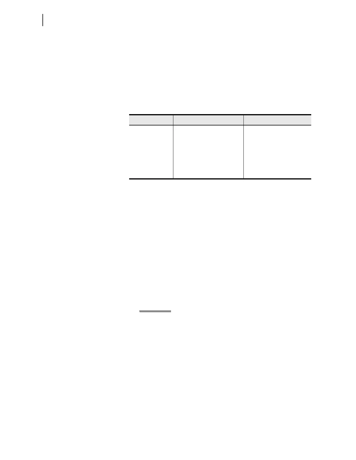
Table 4.55 Shot Counter Correspondence to Relay Word Bits and Open
Interval Times
Shot Corresponding Relay Word Bit Corresponding Open Interval
0 SH0 79OI1
1 SH1 79OI2
2 SH2 79OI3
3 SH3 79OI4
4SH4