2.42
SEL-751 Relay Instruction Manual Date Code 20170927
Installation
Arc-Flash Protection: System Installation
Arc-Flash Protection: System Installation
This section describes an arc-flash system installation, the sensor
characteristics, and an arc-flash application. Refer to Section 4: Protection
and Logic Functions for a description of arc-flash protection and the relay
settings. Section 11: Testing and Troubleshooting gives a description of the
commissioning tests to verify the installation. Also, refer to Application Guide
AG2011-01: Using the SEL-751 and SEL-751A for Arc-Flash Detection,
available on the SEL website, for more details.
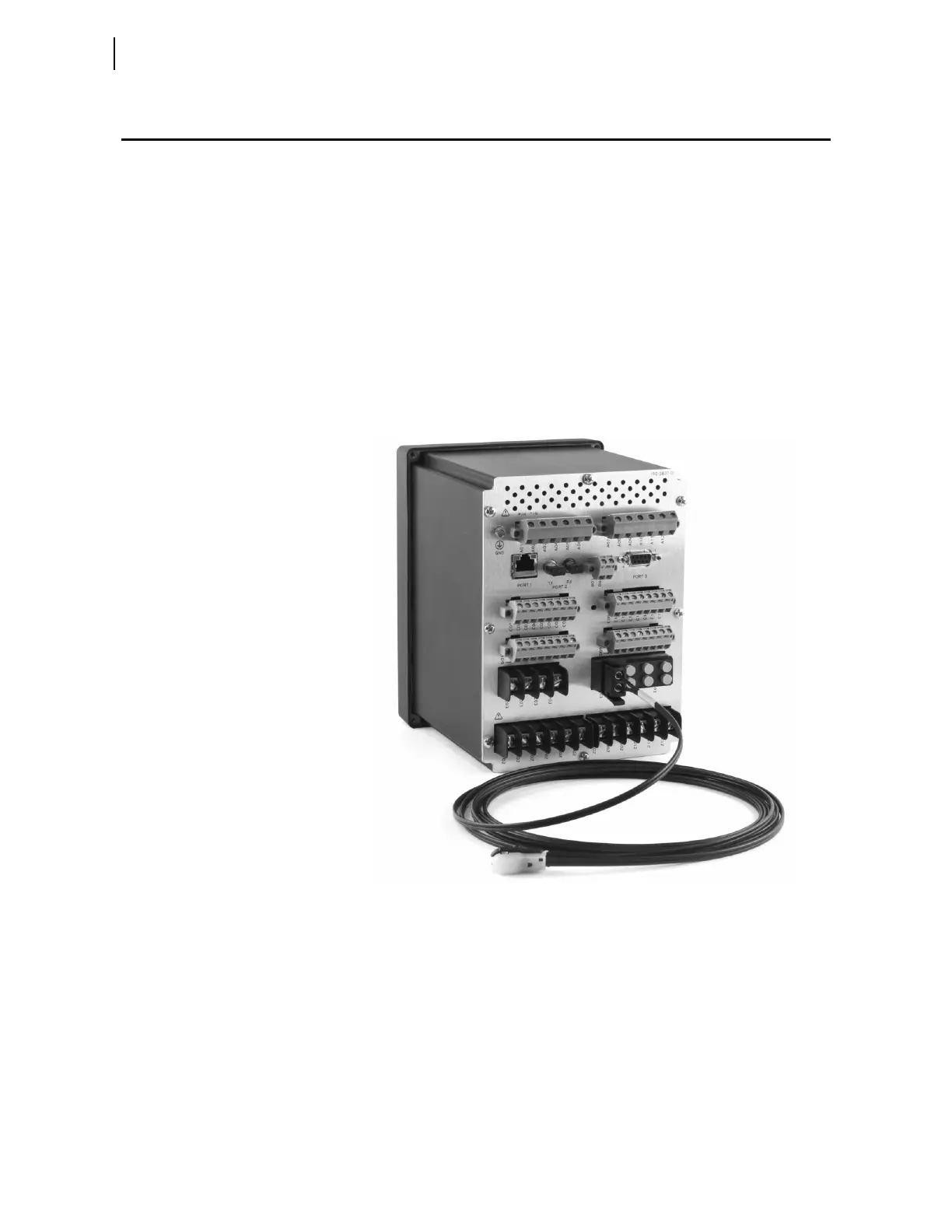
Figure 2.33 shows main system components comprising: current input card,
the arc-flash/voltage input card with sensor terminal block, and the fiber-
optic-based point-sensor assembly. Figure 2.10 shows the rear-panel layout
and the side-panel I/O designations for a relay model with the 2 AVI/4 AFDI
card for arc-flash protection. Figure 2.12 shows the rear-panel layout and the
side-panel I/O designations for a relay model with the 8 AFDI card. Installa-
tion instructions for the 8 AFDI card are similar to the 2 AVI/4 AFDI card.
Figure 2.33 SEL-751 With a 2 AVI/4 AFDI Option Card and the Fiber-Optic-
Based Point-Sensor
Light-Sensor
Installation
An arc-flash system installation starts by selecting the best sensor location
and the safest path for bringing the sensor fibers back to the relay. The actual
sensor location varies depending on the type of switchgear being protected.
Although arc-flash light is easily reflected off painted surfaces, make sure to
avoid shadows/light obstruction caused by the insulating baffles or moving
parts of the breaker truck assembly.
While fiber-optic sensors are inherently nonconductive, they are not intended
for direct contact with energized parts, and must be suspended within 25 mm
(1 in) of the grounded surface. Make sure to observe the original high-voltage