2.29
Date Code 20170927 Instruction Manual SEL-751 Relay
Installation
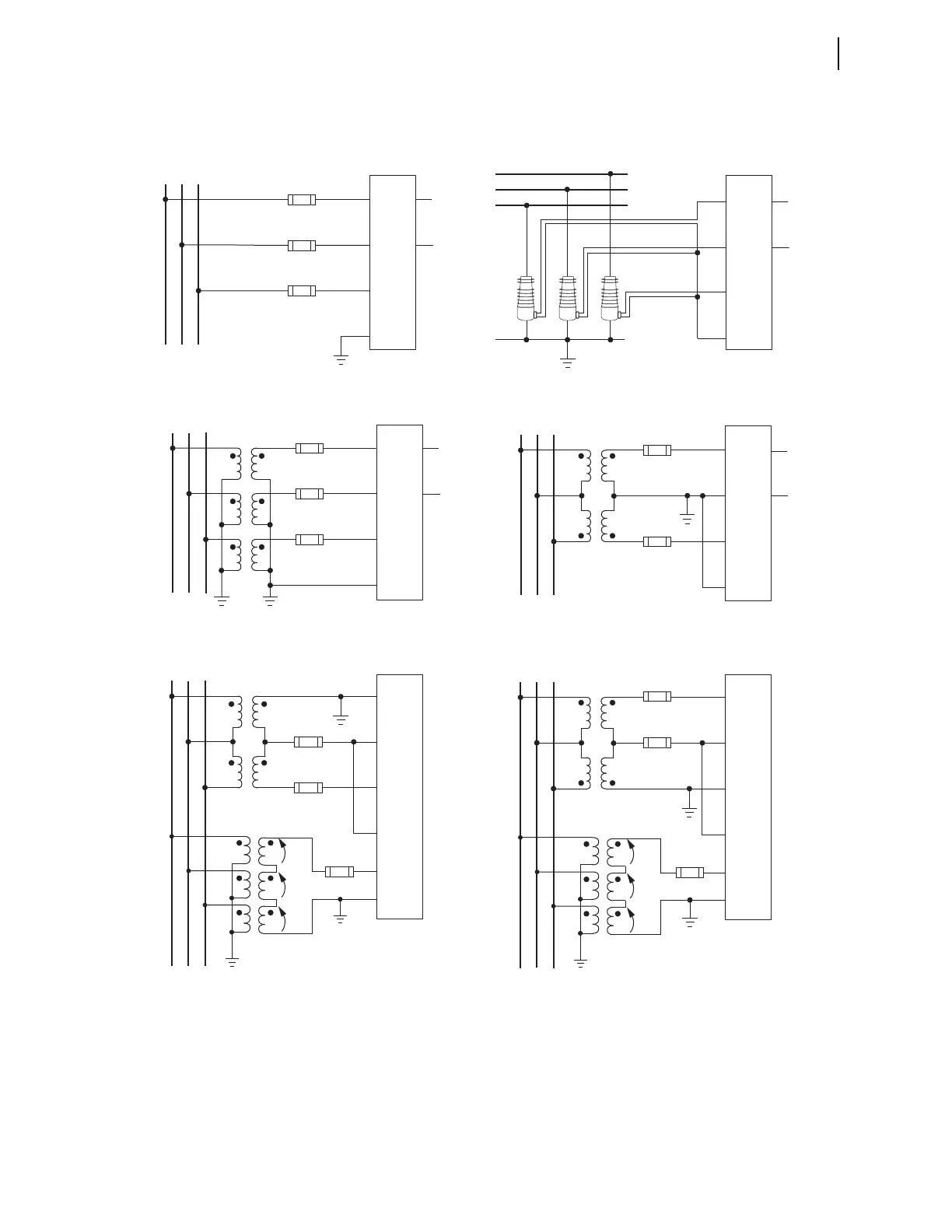
AC/DC Control Connection Diagrams
Figure (b) shows LEA inputs, which support only wye-wye connections. Refer to Under- and Overvoltage Functions on
page 4.97 and LEA Ratio and Angle Correction Factors (Global Settings) on page 4.8 for the LEA settings and ratio
correction factor calculations.
Figure (d) shows an open-delta VT connection with B-Phase (Z10) grounded. You can choose to ground A-Phase or
C-Phase instead of B-Phase, as shown in figures (e) and (f), provided all other connections remain as shown. Terminals
E01 or E02 can be used to input VAB voltage from the bus to the VS/NS input on the relay with NS terminal grounded.
Figure 2.21 Voltage Connections
LEA Sensor
Note: N terminal must be connected to ground. This
is normally accomplished inside the sensor.
(e) Open-Delta and Broken-Delta (3V0) VT Connections
(Set DELTA_Y := DELTA and VSCONN := 3V0)
ABC
ZO9
Z10
Z11
Z12
F2
F3
F4
Broken-Delta
V
A
V
B
V
C
E02
E01
SEL-751
(f) Open-Delta and Broken-Delta (3V0) VT Connections
(Set DELTA_Y := DELTA and VSCONN := 3V0)
ABC
ZO9
Z10
Z11
Z12
Broken-Delta
V
A
V
B
V
C
E02
E01
SEL-751
F1
F2
F4
(a) Direct Connection (Grounded System)
(Set DELTA_Y := WYE)
F1, F2, and F3 are fuses
EO1
EO2
ABC
ZO9
Z10
Z11
Z12
F1
F3
F2
SEL-751
(c) Wye-Wye VT Connection
(Set DELTA_Y := WYE and VSCONN := VS )
EO1
EO2
ABC
ZO9
Z10
Z11
Z12
F1
F3
F2
SEL-751
(d) Open-Delta VT Connection
(Set DELTA_Y := DELTA and VSCONN := VS)
EO1
EO2
ABC
ZO9
Z10
Z11
Z12
F1
F3
SEL-751
(b) Wye-Wye Connected LEA Sensors
(Set DELTA_Y := WYE )
A
B
C
EO1
EO2
ZO9
Z10
Z11
Z12
SEL-751
VS
NS
VA
VB
VC
N
VS
NS
VA
VB
VC
N
VS
NS
VA
VB
VC
N
VA
VC
N
N
VA
VB
VC
N
VS
NS
VA
VB
VC
VS
NS
VB
VS
NS