7.9
Date Code 20170927 Instruction Manual SEL-751 Relay
Communications
Communications Interfaces
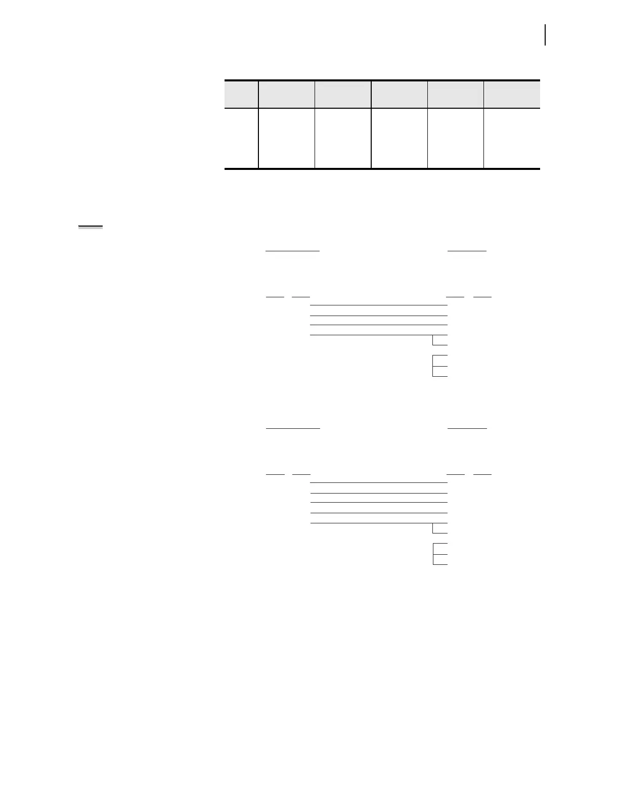
The following cable diagrams show several types of EIA-232 serial
communications cables that connect the SEL-751 to other devices. These and
other cables are available from SEL. Contact the factory for more information.
Figure 7.10 SEL Cable C234A—SEL-751 to DTE Device
Figure 7.11 SEL Cable C227A—SEL-751 to DTE Device
6 IRIG– N/C N/C
7RTS RTS RTS
8CTS CTS CTS
9 GND GND GND
a
For EIA-485, the pin numbers represent relay terminals _O1 through _05.
Table 7.3 EIA-232/EIA-485 Serial Port Pin Functions (Sheet 2 of 2)
Pin
a
PORT 3
EIA-232
PORT 3
EIA-485
a
PORT 4C
EIA-232
PORT 4A
EIA-485
a
PORT F
EIA-232
NOTE: Serial communications
cables that are used in the SEL-751
relays for the M
IRRORED BITS protocol
should have the R designation at the
end of the SEL cable number instead
of an A; for example, use SEL Cable
C234R instead of SEL Cable C234A.
SEL-751 Relay
9-Pin Male
D Subconnector
9-Pin Female
D Subconnector
2
3
5
8
3
2
5
8
7
1
4
6
RXD
TXD
GND
CTS
TXD
RXD
GND
CTS
RTS
DCD
DTR
DSR
Pin
Func.
Pin
Func.
Pin # Pin #
*DTE Device
*DTE = Data Terminal Equipment (Computer, Terminal, etc.)
SEL-751 Relay
9-Pin Male
D Subconnector
25-Pin Female
D Subconnector
5
3
2
9
8
7
3
2
1
4
5
6
8
20
GND
TXD
RXD
GND
CTS
GND
RXD
TXD
GND
RTS
CTS
DSR
DCD
DTR
Pin
Func.
Pin
Func.
Pin # Pin #
*DTE Device
*DTE = Data Terminal Equipment (Computer, Terminal, etc.)